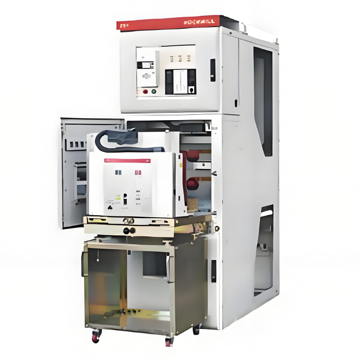
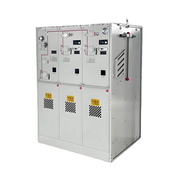
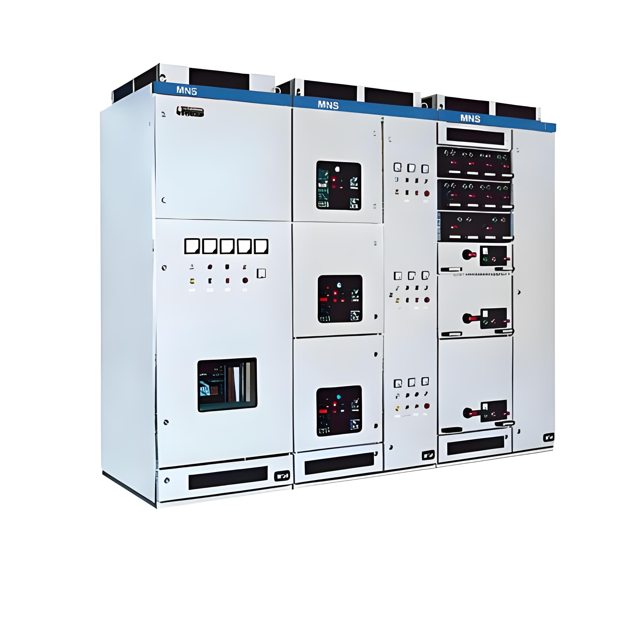
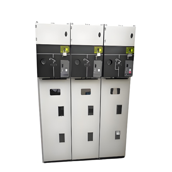
3.6kV-24kV Indoor metal-clad withdrawable switchgear MV Switchgear
discuss personally
Model
| Brand | ROCKWILL |
| Model NO. | 3.6KV-24KV Indoor metal-clad withdrawable switchgear MV Switchgear |
| Rated voltage | 7.2kV |
| Series | KYN28-12 |
Description:
China KYN28-12 indoor metal-clad withdrawable switchgear (hereinafter short as switchgear) is a complete power distribution device for 3.6~24kV,3-phase AC 50Hz,single-bus and single-bus sectionalized system. It is mainly used for power transmission of middle/small generators in power plants; power receiving, transmission for substations in power distribution and power system of factories, mines and enterprises, and starting of large high-voltage motor, etc.,so as to control, protect and monitor the system. The switchgear meets IEC298,GB3906-91.In addition to be used with domestic VS1 vacuum circuit breaker, it can also be used with VD4 from ABB,3AH5 from Siemens domestic ZN65A,and VB2 from GE, etc.,it is truly a power distribution device with good performance. In order to meet the requirement for wall mounting and front-end maintenance, the switchgear is equipped with a special current transformer, so that the operator can maintain and inspect it in front of the cubicle.
Ambient temperature: Maximum temperature:+40℃ Minimum temperature: -15℃.
Ambient humidity: Daily average RH no more than 95%;Monthly average RH no more than 90%.
Altitude no higher than 2500m.
The air around without any pollution of duty,smoke,ercode or flammable air,steam or salty fog.
Technical parameters:

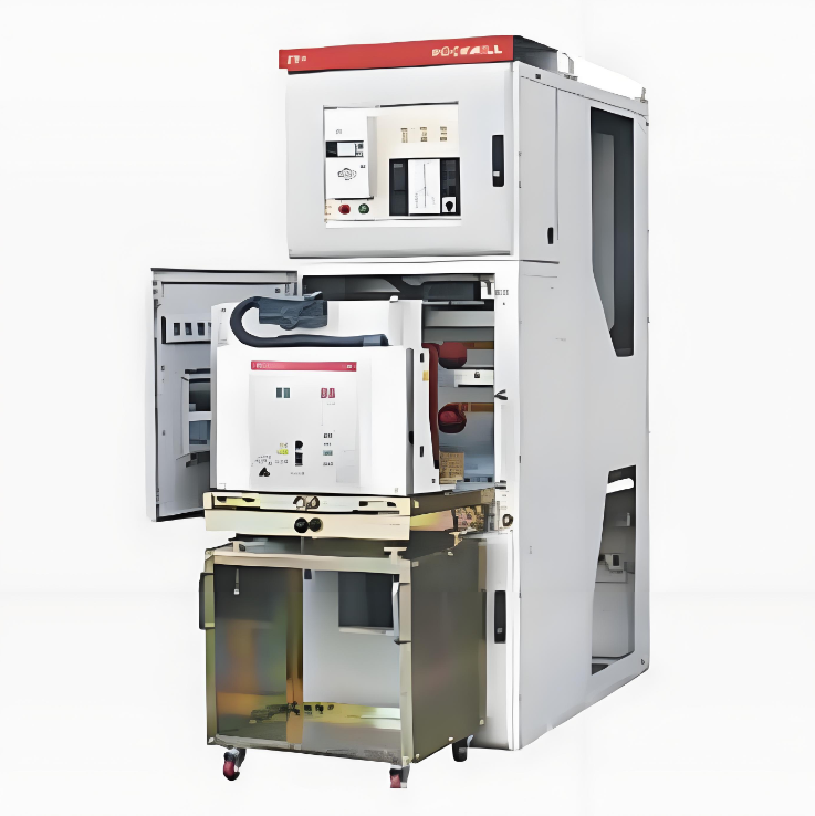
Structure & Basic Components of Switchgear:

Overall size and weight:

Notice:
when the rated current is more than 1600A, cubicle width shall de 1000 mm, and cubicle height will be 1660mm and for schema of rear overhead line in.
Width of cabinet:650mm(compound insulation)or 800mm(air insulation) at current<1250A.
Width of cabinet:1000mm at current>1250A.
Depth of cabinet:1400mm,at cabinet width of 650mm(compoud insulation)when employing theconfiguration of incoming and outgoing cables.
Depth of cabinet:1500mm,at cabinet width of 6800mm(air insulation)when employing theconfiguration of incoming and outgoing cables.
Depth of cabinet:1600mm,when employing the configuration of rear overhead incoming andoutgoing cables.

Structure Features:

Compartment:
Busbar compartment; circuit breaker compartment; cable compartment; low-voltage compartment.
Main device: circuit breaker, contactor.
Current transformers.
Earthing switch.
Voltage transformers.
Support-bushing insulators.
Bushing insulators.
Surge arresters.
Support insulators (reactance).
Main busbars.
Connecting (distribution) busbars.
Earth-fault current transformer.
Earthing conductor.
Metal movable particions.
Cable ducts (optionally).
Vent flaps.
Dimension:

Dimension in brackets means dimension of heavy-current cubicle.

What are the application scenarios of indoor metal armored pull-out switch cabinets?
In Industrial Enterprises:
Widely used in factories, mines, metallurgy, and chemical industries. They provide medium-voltage power distribution and protection for various production equipment such as large motors, transformers, and electric furnaces. For example, in a steel mill's rolling workshop, medium-voltage switchgear provides reliable power supply to the rolling motors and can quickly cut off the circuit in case of motor overload or short circuit, protecting the motor and the entire production line.
In Commercial Buildings (e.g., shopping centers, office buildings, hotels) and Public Facilities (e.g., hospitals, schools, stadiums):
Used in medium-voltage distribution rooms. They provide power distribution and control for equipment within the buildings, such as elevators, air conditioning, and lighting. For instance, in a hospital, medium-voltage switchgear supplies stable power to various medical equipment and air conditioning systems, ensuring the normal operation of the hospital.
In Medium-Voltage Substations:
Serves as the primary distribution equipment, receiving and distributing power from transmission lines. It can step down the medium-voltage power from the transmission lines and distribute it to various low-voltage lines, or distribute the power to other substations or end-users.