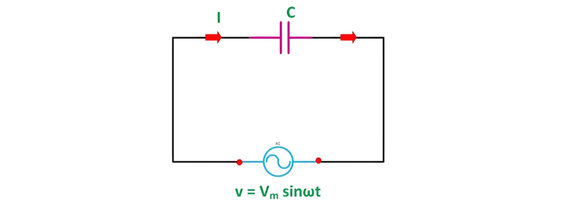
Pure Capacitor Circuit
A circuit comprising only a pure capacitor with capacitance C (measured in farads) is termed a Pure Capacitor Circuit. Capacitors store electrical energy within an electric field, a characteristic known as capacitance (alternatively referred to as a "condenser"). Structurally, a capacitor consists of two conductive plates separated by a dielectric medium—common dielectric materials include glass, paper, mica, and oxide layers. In an ideal AC capacitor circuit, the current leads the voltage by a phase angle of 90 degrees.
When voltage is applied across a capacitor, an electric field is established between its plates, but no current traverses the dielectric. With a fluctuating AC voltage source, continuous current flow occurs due to the capacitor’s cyclic charging and discharging processes.
Explanation and Derivation of Capacitor Circuit
A capacitor comprises two insulated plates separated by a dielectric medium, serving as an energy storage device for electrical charge. It charges when connected to a power source and discharges when disconnected. When linked to a DC supply, it charges to a voltage equal to the applied potential, exemplifying its role as a passive electrical component that resists changes in voltage.
Let the alternating voltage applied to the circuit is given by the equation:
Charge of the capacitor at any instant of time is given as:
Current flowing through the circuit is given by the equation:
Putting the value of q from the equation (2) in equation (3) we will get
Now, putting the value of v from the equation (1) in the equation (3) we will get
Where Xc = 1/ωC denotes the opposition to alternating current flow by a pure capacitor, known as capacitive reactance.The current reaches its maximum value when sin(ωt + π/2) = 1.Thus, the maximum current Im is expressed as:
Substituting the value of Im in the equation (4) we will get:

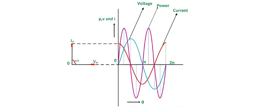
Phasor Diagram and Power Curve
In a pure capacitor circuit, the current through the capacitor leads the voltage by a 90-degree phase angle. The phasor diagram and waveforms for voltage, current, and power are illustrated below:
In the waveform above, the red curve represents the current, the blue curve denotes the voltage, and the pink curve indicates the power. When the voltage increases, the capacitor charges to its maximum value, forming a positive half-cycle; as the voltage decreases, the capacitor discharges, creating a negative half-cycle. A careful examination of the curve reveals that when the voltage reaches its peak, the current drops to zero, meaning no current flows at that instant. As the voltage decreases to π and turns negative, the current peaks, triggering the capacitor to discharge—and this charging-discharging cycle continues.
Voltage and current never reach their maxima simultaneously due to their 90° phase difference, as shown in the phasor diagram where the current (Im) leads the voltage (Vm) by π/2. The instantaneous power in this pure capacitor circuit is defined by p = vi.
Thus, it can be deduced from the above equation that the average power in a capacitive circuit is zero. The average power over a half-cycle equals zero due to the symmetry of the waveform, where the positive and negative loop areas are identical.
During the first quarter-cycle, power supplied by the source is stored within the electric field established between the capacitor plates. In the subsequent quarter-cycle, as the electric field dissipates, the stored energy is returned to the source. This cyclic process of energy storage and return occurs continuously, resulting in no net power consumption by the capacitor circuit.