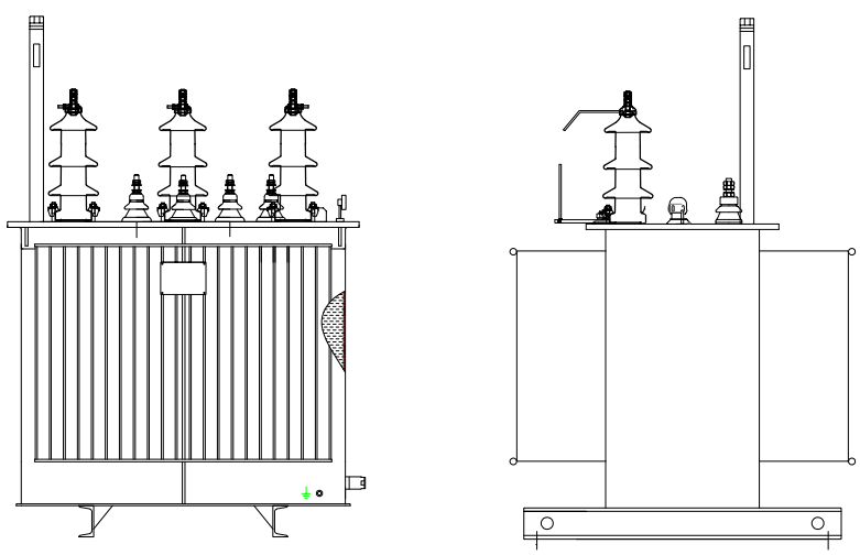
• 100kVA 15kV 3 Phase Oil-immersed distribution transformer
100kVA 15kV 3 Phase Oil-immersed distribution transformer
discuss personally
Model
S-M-15KV-100KVA
S-15KV-0.4KV-25KVA
S-30KV-0.4KV-500KVA
S-M-15KV-0.4KV-160KVA
S-15KV-0.4KV-250KVA
S-15KV-0.4KV-2000KVA
S-15KV-0.4KV-500KVA
S-15K-1000KVA
S-M-30KV-50KVA
S-M-30KV-0.4KV-25KVA
S-M-20KV-250KVA
S-M-15KV-50KVA
S-30KV-0.4KV-630KVA
S-M-30KV-1000KVA
S-30KV-400KVA
S-M-30KV-160KVA
S-M-30KV-100KVA
S-M-30KV-50KVA
S-15KV-25KVA
S-M-30KVA-100KVA
S-M-30KV-0.4KV-50KV
S-M-30KV-0.4KV-100KVA
S-M-33KV-0.4KV-50KVA
S-M-30KV-0.4KV-25KVA
RCW-380V
S-M-15Kv-0.4KV-100KVA
Basic info
Brand Vziman
Model NO. 100KVA 15KV 3 PhaseOil-immersed distribution transformer
Rated voltage 15kV
Rated capacity 100kVA
Primary voltage
Secondary voltage
No-load loss
Load loss
Series S-M
Product Detail

Description:

Oil immersed transformer, use ourcompany special calculation and validation procedures to make sure theperformance of products. superior process equipment, elaborate materialselecting and efficient manufacturing make the transformer have smallvolume,light weight,low loss,low partial discharge,low noise characteristics.

The product is stable,reliable,economic, environmental protection. lt can beapplied to many places such as power plants,transformer substation ,largeindustrial mining and petrochemical enterprise and so on.

Features:

  • Ultralow no-load loss.

  • Energy saving and great power consuming efficiency.

  • Copper/ aluminum coil winding, strong short circuit resistance ability.

  • Dyn11 coil connection decrease the influences of harmonic wave.

  • Fully sealed structure for maintenance free.

  • Slow insulation aging & longer serving life.

Parameters:

Oil-immersed distribution transformer three-phase

Model NO.

S-M-100/15/0.4

Product classification

Distribution transformer

Rated capacity

100kVA

Primary voltage

15kV

Secondary voltage

0.4kV

Number of phase

3

Number of winding

2

Rated frequency

50Hz

Tap changer

OCTC

Tap range

±2×2.5%

Vector group

Dyn11

Cooling system

ONAN

No-load loss

>320W

Load loss

>170W

Impedance

4%

Basic insulation level

——

Winding material ( H.V & L.V)

Copper

The way the bushing appears

Porcelain

Power frequency withstand voltage

38kV

Lightning impulse

——

The temperature rise—Winding

62k

The temperature rise --Top oil

57k

Tank color

——

Creepage distance

>576mm

Fitting requirement

——

Environmental requirement

——

Transformer structure

Sealed

Standard

IEC60076

Port of loading

——

HS code

——

Transportation

——


External dimensions:

企业微信截图_17103775276834.png

Size

885mm×875mm×1120mm

Weight

590KG

Environmental requirement:

Max. ambient temperature

——

Altitude

——


Product show:

Yawei 160kVA 10kv Hot Selling Oil-Filled Three-Phase Distribution Transformer with UL


 How to choose the model and specification of oil-immersed three-phase distribution transformer according to load capacity?


Selecting a Transformer Based on Load Capacity:

Calculate Total Load Power:

  • First, it is necessary to determine the total power of the loads to be supplied. For residential areas, this involves considering the total power of all household electrical appliances, including lighting fixtures, televisions, refrigerators, air conditioners, etc. For example, in a residential area with 100 households, if the average power consumption per household is 5 kW (considering the simultaneous use factor), the total load power would be approximately 500 kW.

  • In industrial settings, it is necessary to tally the power of all production equipment, lighting, and office devices within the factory. For instance, in a small mechanical processing plant, the total power of machine tools might be 300 kW, and adding the power of lighting and office devices, the total load power could reach around 350 kW.

Consider Simultaneous Factor and Power Factor:

  • The simultaneous factor refers to the probability that all loads will operate simultaneously at any given moment. In residential areas, the simultaneous factor is generally between 0.4 and 0.6. In industrial settings, it is determined based on production shifts and equipment operating patterns, typically ranging from 0.7 to 0.9.

  • The power factor reflects the efficiency of energy utilization by the load. In scenarios with a high proportion of inductive loads (such as motors), the power factor is lower, usually between 0.7 and 0.9. It is essential to calculate based on actual load conditions and then select the transformer capacity based on the calculated actual load capacity.

Know your supplier
Vziman
Zhejiang Vziman Electric Group Co., Ltd. is a high-tech enterprise specializing in R&D, manufacturing, and service of power electrical equipment. Committed to innovation, quality, and customer satisfaction, it supplies smart solutions for global power sectors, covering grid construction, new energy, and industrial distribution. Core Business • Switchgear (GIS, circuit breakers, Recloser, Load break switch) • Distribution equipment (transformers, RMU, smart terminals) • Power automation systems • Engineering services (installation, maintenance, consulting) Technical Strength • Provincial R&D center, multiple patents • Modern production, ISO/GB/IEC/CE/UL certified • High capacity, large-scale delivery support Market & Vision Serves State Grid, Southern Grid, and global projects (Asia, Africa, Europe, etc.). Aims to lead in smart grids and new energy, promoting sustainable energy development.
Main Categories
High voltage
Business Type
Design/Manufacture/Sales
Highest Annual Export (USD)
$150000000
Professional Experience
3 years
Workplace
10000m²
占位
占位
Related Products
Related Knowledges
The design of the three-purpose grounding transformer
Underground Power Cable Transmission LinesDirect - buried power cable lines have large ground - distributed capacitance, causing high single - phase - to - ground short - circuit capacitive current. For 10 kV lines, if this current exceeds 10 A, arcs hardly self - extinguish, risking arc overvoltage and endangering line equipment. Arc extinction is thus necessary. With a Dyn - connected main transformer, an arc - suppression coil on the secondary neutral point suffices. For Yd - connected ones,
Dyson
06/12/2025
Failure Analysis and Design Optimization of Conventional Grounding Transformers
I. Core Cause of Damage: Electrodynamic Impact (Complying with GB/T 1094.5 / IEC 60076-5)The direct cause of high-voltage winding end collapse is the instantaneous electrodynamic impact induced by short-circuit current. When a single-phase grounding fault occurs in the system (such as lightning overvoltage, insulation breakdown, etc.), the grounding transformer, as the fault current path, withstands high-amplitude and steep-rise-rate short-circuit currents. According to Ampère's force law
Felix Spark
06/12/2025
Analysis of Grounding Transformer Operational Behavior Under System Single-Phase-to-Ground Fault Conditions
1 Theoretical AnalysisIn distribution networks, grounding transformers serve two key roles: powering low - voltage loads and connecting arc - suppression coils at neutrals for grounding protection. Grounding faults, the most common distribution network fault, heavily impact transformers’ operating characteristics, causing sharp changes in electromagnetic parameters and status.To study transformers’ dynamic behaviors under single - phase grounding faults, build this model: Assume a tr
Felix Spark
06/12/2025
Design Calculations for Neutral Grounding Schemes and Grounding Transformer Sizing in Utility-Scale Solar PV Plants
1 Classification of Neutral Grounding Methods for Solar Photovoltaic Power StationsInfluenced by differences in voltage levels and grid structures across regions, the neutral grounding methods of power systems are mainly categorized into non-effective grounding and effective grounding. Non-effective grounding includes neutral grounding via arc suppression coils and neutral ungrounded systems, while effective grounding comprises neutral solid grounding and neutral grounding via resistors. The sel
Dyson
06/12/2025
Zero-Sequence Impedance Characterization of Dry-Type Grounding Transformer with ZN Connection
In a neutral-insulated three-phase power system, an earthing transformer provides an artificial neutral point, which can be solidly earthed or earthed via reactors/arc suppression coils. The ZNyn11 connection is typical, where zero-sequence magnetomotive forces in the inner/outer half-windings of the same core column cancel out, balancing fault currents in series windings and minimizing zero-sequence leakage flux/impedance.Zero-sequence impedance is critical: it determines fault current magnitud
Dyson
06/12/2025
Case Analysis on Maloperation of Grounding Transformer Overcurrent Protection Relay
The neutral grounding mode refers to the connection between the power system neutral point and ground. In China's 35 kV and below systems, common methods include ungrounded neutral, arc-suppression coil grounding, and small-resistance grounding. The ungrounded mode is widely used as it allows short-term operation during single-phase grounding faults, while small-resistance grounding has become mainstream for its fast fault removal and overvoltage limitation. Many substations install grounding tr
Felix Spark
06/12/2025
×
Inquiry
Download
Experts Electrical is dedicated to serving the personnel in the global power industry.
Join Experts Electrical, not only can you discover power equipment and power knowledge, but also canhnd like - minded friends!
商品视频播放