Operation Method for PT Resonance in 500kV GIS Switching Station

James
07/08/2025


Topics
Professionalism builds strength. As an expert in the installation and operation of electrical equipment, I am proficient in the installation process and strictly adhere to standards. I skillfully master the operation essentials and can swiftly eliminate faults. With a heart that constantly explores new knowledge, I illuminate the path to the efficient operation of electrical equipment.
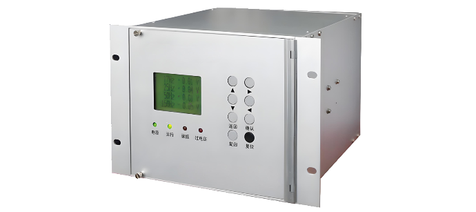
What should be noted when selecting and installing GIS voltage transformers?
In power systems, voltage transformers in GIS (Gas Insulated Switchgear) play a crucial role in voltage measurement and relay protection. Selecting the right model and installing it correctly is vital for the stable operation of the equipment. The following points should be noted regarding selection and installation.I. Key Points for Selection(1) Matching Rated ParametersVoltage Level: It must be consistent with the voltage level of the GIS system. For example, 110kV and 220kV GIS systems requir
James
07/08/2025
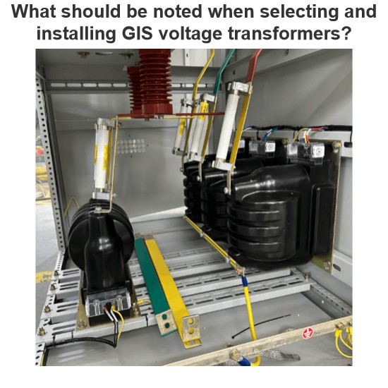
What are the causes of the breakdown and burning of the 35 kV GIS voltage transformer?
1. Accident Overview1.1 Structure and Connection of 35kV GIS Switchgear Voltage TransformerThe ZX2 gas-insulated double-bus switchgear, manufactured in March 2011 and officially put into operation in July 2012, is configured with two groups of bus voltage transformers (PTs) for each bus section. The two PT groups of the same bus section are designed in one switchgear cabinet with a width of 600 mm. The three-phase PTs are arranged in a triangular formation at the bottom of the cabinet.The PTs ar
Felix Spark
07/08/2025
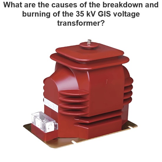
What Are the Steps for Error Testing GIS Voltage Transformers?
Hey everyone, I'm Oliver, and I've been working with current transformers (CTs) and voltage transformers (VTs) for 8 years.From assisting my mentor on site to leading high-voltage testing teams and conducting error calibrations independently, I’ve dealt with all kinds of instrument transformers — especially those used in GIS systems. The error test for voltage transformers is something I perform regularly.A few days ago, a friend asked me:“Oliver, how exactly do you perform an
Oliver Watts
07/08/2025
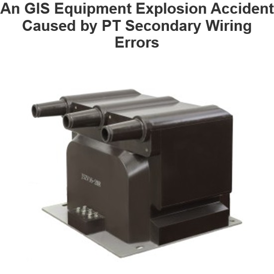
An GIS Equipment Explosion Accident Caused by PT Secondary Wiring Errors
1. Accident OverviewA newly - built 110kV substation’s GIS exploded during commissioning due to a PT secondary circuit short - circuit. Though the cause was simple, consequences were severe, warranting reflection.2. Accident ProcessOn the power - transmission day:The upper - level power supply charged the 110kV GIS (a combined appliance).20s after closing the incoming switch and first live - impacting the 110kV bus, white smoke emerged between the PT compartment and control cabinet.Within
Felix Spark
07/08/2025


