An GIS Equipment Explosion Accident Caused by PT Secondary Wiring Errors

Felix Spark
07/08/2025

1. Accident Overview
A newly - built 110kV substation’s GIS exploded during commissioning due to a PT secondary circuit short - circuit. Though the cause was simple, consequences were severe, warranting reflection.
2. Accident Process
On the power - transmission day:
  • The upper - level power supply charged the 110kV GIS (a combined appliance).
  • 20s after closing the incoming switch and first live - impacting the 110kV bus, white smoke emerged between the PT compartment and control cabinet.
  • Within ten seconds, the bus PT’s GIS compartment exploded. The upper power tripped; the PT compartment’s disc insulator burst, filling the GIS room with insulator fragments and SF₆ combustion by - products.
3. Cause Analysis
3.1 On - site Investigation
The 110kV PT (Shanghai MWB, electromagnetic type) had:
  • 1 basic secondary winding: 100/√3 V (150VA, 0.2 class).
  • 1 auxiliary secondary winding: 100V (150VA, 3P class), unused per design (routed to the control cabinet terminal block, no external connection).
Key findings:
  • Phase C: Severe PT secondary winding insulation burns; basic winding conductor charred. Auxiliary winding conductor insulation totally burned; insulation cylinder between auxiliary winding & iron core charred. Insulation resistance between basic & auxiliary windings = 0.
  • Phase B: Basic secondary winding outer insulation had burning marks; internal paint film intact. Auxiliary winding surface insulation showed overheating charring.
  • Phase A: Slight basic secondary winding surface insulation burn; other conductors/insulation intact.

Preliminary conclusion: PT secondary circuit short - circuit, likely in B/C phase auxiliary windings.
Further control cabinet inspection: B/C phase auxiliary windings were shorted inside. Design - intended connections (C - ncf to terminal 11, B - nbf to terminal 15) were misrouted (C - ncf to 12, shorting to 14 - cf; B - nbf to 16, shorting to 18 - bf).
3.2 Accident Development
  • Short - circuit start: After primary system closure, B/C phase auxiliary windings (cf, ncf; bf, nbf) shorted → B/C voltage drop.
  • B phase short - circuit end: After 20s, B phase short - circuit disconnected (primary lead burned by arc). Short time caused only B auxiliary winding overheating.
  • C phase consequence: 43s short - circuit (per accident recording) overheated C phase secondary conductor → insulation melt/char. White smoke came from this.
  • Insulation failure: PT auxiliary winding insulation melt degraded SF₆ gas in the PT chamber → lower insulation level.
  • Discharges: Reduced insulation + close phase - to - ground distances → A/B/C phases discharged to GIS shell.
  • Explosion: Arc energy raised gas chamber pressure → PT disc insulator burst.

3.3 Human Error
During commissioning:
  • Technicians rechecked PT polarity/insulation.
  • For convenience, they removed the PT secondary circuit from the control cabinet terminal block.
  • Mistakenly shorted B/C phase auxiliary winding ends; failed to verify → B/C auxiliary windings shorted.
4. Preventive Measures
4.1 PT Secondary Circuit Safety
Short - circuits in PT secondary circuits damage components or burn PTs. Installed in a closed GIS chamber, PT faults cause explosions (risking injury, delaying repairs). Thus, GIS PT installation/wiring demands strict attention.
4.2 Secondary Circuit Protocols
“Electrical Safety Work Regulations” and “Relay Protection On - site Work Security Regulations” mandate secondary work safety tickets for disassembly/wiring. Using these (and integrating risk control) could have prevented wrong wiring amid workload/time pressures.
4.3 Pre - energization Testing
Strengthen pre - energization PT tests (standardized, documented). Enforce strict test execution to avoid errors from careless work.
4.4 Organizational & Protection Measures
Protect commissioned equipment (lock cabinets, use seals). Modify only post - approval; have supervised restoration.
4.5 Unused Circuit Removal
Remove unused secondary circuits (reduce error risks). Here, the unused auxiliary winding (routed to the control cabinet) caused the accident via miswiring.
4.6 PT Body Air Switch
Install secondary air switches in PT body wiring boxes (current setup in control cabinets can’t protect GIS - to - PT circuits). This isolates faults below the PT secondary outlet.By reconstructing the accident, analyzing causes, and proposing 6 preventive measures, a roadmap for GIS secondary circuit safety is established.
Felix Spark

Hey there! I'm an electrical engineer specializing in Failure and Maintenance. I've dedicated my career to ensuring the seamless operation of electrical systems. I excel at diagnosing complex electrical failures, from malfunctioning industrial motors to glitchy power distribution networks. Using state - of - the - art diagnostic tools and my in - depth knowledge, I pinpoint issues quickly. On this platform, I'm eager to share my insights, exchange ideas, and collaborate with fellow experts. Let's work together to enhance the reliability of electrical setups.

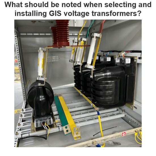
What should be noted when selecting and installing GIS voltage transformers?
In power systems, voltage transformers in GIS (Gas Insulated Switchgear) play a crucial role in voltage measurement and relay protection. Selecting the right model and installing it correctly is vital for the stable operation of the equipment. The following points should be noted regarding selection and installation.I. Key Points for Selection(1) Matching Rated ParametersVoltage Level: It must be consistent with the voltage level of the GIS system. For example, 110kV and 220kV GIS systems requir
James
07/08/2025
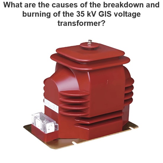
What are the causes of the breakdown and burning of the 35 kV GIS voltage transformer?
1. Accident Overview1.1 Structure and Connection of 35kV GIS Switchgear Voltage TransformerThe ZX2 gas-insulated double-bus switchgear, manufactured in March 2011 and officially put into operation in July 2012, is configured with two groups of bus voltage transformers (PTs) for each bus section. The two PT groups of the same bus section are designed in one switchgear cabinet with a width of 600 mm. The three-phase PTs are arranged in a triangular formation at the bottom of the cabinet.The PTs ar
Felix Spark
07/08/2025
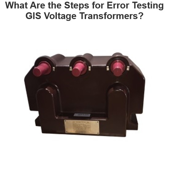
What Are the Steps for Error Testing GIS Voltage Transformers?
Hey everyone, I'm Oliver, and I've been working with current transformers (CTs) and voltage transformers (VTs) for 8 years.From assisting my mentor on site to leading high-voltage testing teams and conducting error calibrations independently, I’ve dealt with all kinds of instrument transformers — especially those used in GIS systems. The error test for voltage transformers is something I perform regularly.A few days ago, a friend asked me:“Oliver, how exactly do you perform an
Oliver Watts
07/08/2025
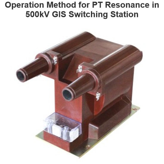
Operation Method for PT Resonance in 500kV GIS Switching Station
1. Causes of ResonanceA 500kV GIS switching station is designed following the principle of “primary equipment intelligence and secondary equipment networking”. The PT high - voltage side has no disconnector and is directly connected to the bus GIS. Through the analysis of fault recording diagrams, when the 5021 circuit breaker opens, the fracture capacitance and PT form a series circuit. Moreover, the bus voltage, after being paralleled by the PT inductance, shows inductive character
James
07/08/2025
Inquiry
Download
Experts Electrical is dedicated to serving the personnel in the global power industry.
Join Experts Electrical, not only can you discover power equipment and power knowledge, but also canhnd like - minded friends!