• 500 kV Dry-Type Shunt Reactor consist only of encapsulated windings
  • 500 kV Dry-Type Shunt Reactor consist only of encapsulated windings
500 kV Dry-Type Shunt Reactor consist only of encapsulated windings
discuss personally
Model
SR-500
Basic info
Brand Wone
Model NO. New 500 kV Shunt Reactor
Rated voltage 500KV
Series SR
Product Detail

Description:

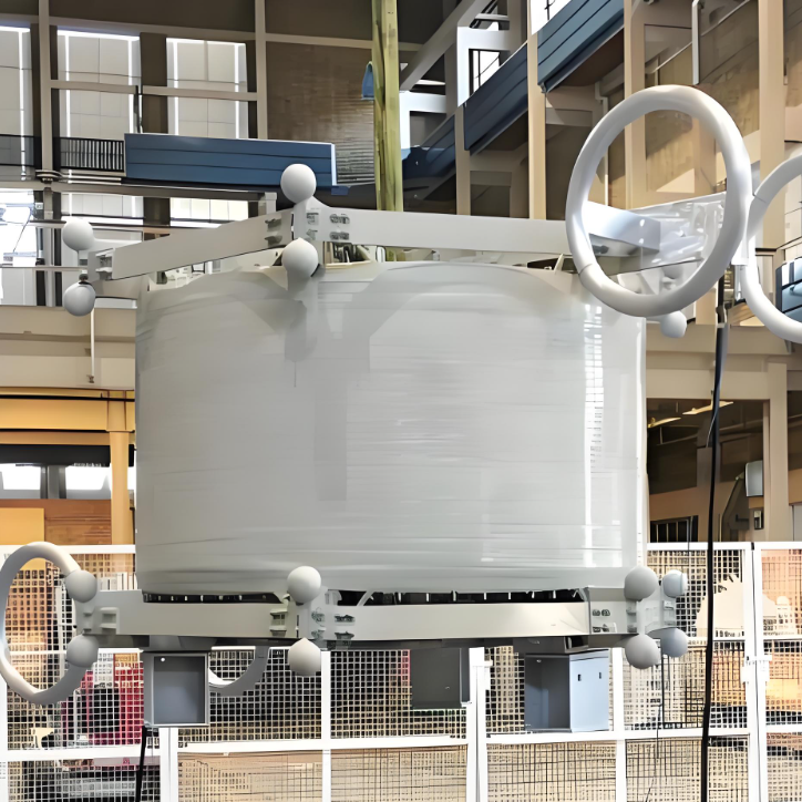
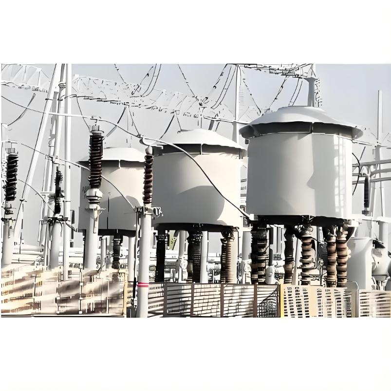
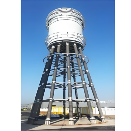
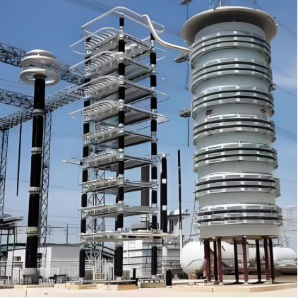
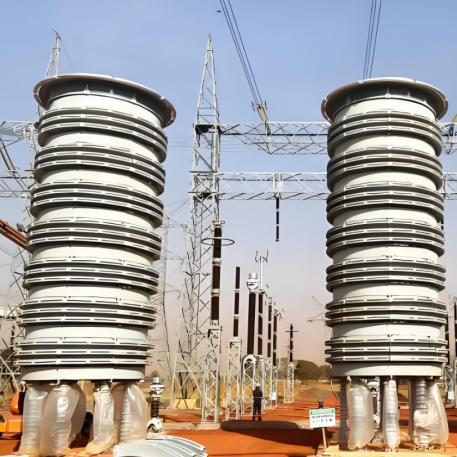
Shunt reactors are connected in a parallel configuration to the power system to compensate for capacitive reactive power of transmission and distribution systems. This ensures that operating voltages are maintained within acceptable operating levels.

Shunt reactors are constructed as either “Oil-Immersed ” or “Dry-Type”.

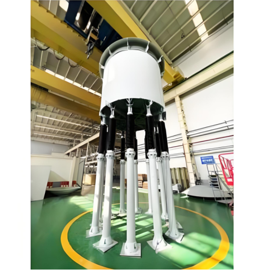
Dry-Type reactors consist only of encapsulated windings, supported by the appropriate insulators.

Feature:

  • Special “Modular” Design which is more compact.

  •  Good voltage equalizing performance, excellecnt tolerance to transient overvoltage.

  •  No iron core, low vibration, low noise.

  •  Only 20% of the weight of oil reactor, less occupation of land, completely replace the oil reactor, maintenance-free.

  •  Low heat generation, rain proof, bird proof, good weather resistance and more reliable.

  •  Easy assembly and disassembly, fast and convenient transportation, great anti-seismic structure.

  •  Replaces Oil-Immersed shunt reactors and traditional Dry-Type Shunt Reactors.

Parameters:

image.png

How does a dry shunt reactor work?

Limiting Overvoltage:

  • In weak electrical systems, when the short-circuit power is relatively low, voltage increases due to capacitive generation. As the network's short-circuit power increases, the magnitude of voltage increase decreases, thereby reducing the need for compensation to limit overvoltage.

Limiting Reactive Power Transfer:

  • Reactors can achieve reactive power balance across different parts of the network. This is especially important in heavily loaded networks where new lines cannot be constructed due to environmental reasons. Reactors used for this purpose are mostly thyristor-controlled to rapidly adapt to the required reactive power. For instance, in industrial areas with arc furnaces, reactive power demand fluctuates between each half-cycle. Typically, a combination of Thyristor-Controlled Reactors (TCR) and Thyristor-Switched Capacitor banks (TSC) is used to absorb and generate reactive power based on instantaneous demand.

Extinguishing Secondary Arcs:

  • During single-phase reclosing in long transmission lines, interphase capacitive coupling can provide a current that sustains the arc, known as the secondary arc. By adding a single-phase reactor at the neutral point, the secondary arc can be extinguished, improving the success rate of single-phase automatic reclosing.


Know your supplier
Wone
Main Categories
High voltage/Low voltage/Wire cable/Instrument meters/New energy/Tester/Production equipment/Generator/Electrical fittings/Integrated Electrical Equipment
Business Type
Design/Manufacture/Sales
Highest Annual Export (USD)
$50,000,000
Professional Experience
1 years
Workplace
65666m²m²
占位
占位
Related Products
Related Knowledges
What is Transformer Vector Groups?
Transformer Vector Group DefinitionThe transformer vector group denotes the phase difference between the primary and secondary sides of a transformer, while also defining the arrangement of high-voltage and low-voltage windings in three-phase transformers. Vector groups are determined by the connection configurations of three-phase transformers, which can be categorized into four main groups based on the phase difference between corresponding line voltages of the high-voltage and low-voltage sid
Edwiin
06/02/2025
What is a Pure Resistive AC Circuit?
Pure Resistive AC CircuitA circuit containing only a pure resistanceR(in ohms) in an AC system is defined as a Pure Resistive AC Circuit, devoid of inductance and capacitance. Alternating current and voltage in such a circuit oscillate bidirectionally, generating a sine wave (sinusoidal waveform). In this configuration, power is dissipated by the resistor, with voltage and current in perfect phase—both reaching their peak values simultaneously. As a passive component, the resistor neither
Edwiin
06/02/2025
What is a Pure Capacitor Circuit?
Pure Capacitor CircuitA circuit comprising only a pure capacitor with capacitanceC(measured in farads) is termed a Pure Capacitor Circuit. Capacitors store electrical energy within an electric field, a characteristic known ascapacitance(alternatively referred to as a "condenser"). Structurally, a capacitor consists of two conductive plates separated by a dielectric medium—common dielectric materials include glass, paper, mica, and oxide layers. In an ideal AC capacitor circuit, the current
Edwiin
06/02/2025
Resonant Frequency
Resonant Frequency
In a series circuit, the resonant frequency condition occurs when the inductive reactance equals the capacitive reactance. Changing the supply frequency alters the values of XL = 2πfL and XC = 1/2πfC.As the frequency increases, XL rises whileXC falls. Conversely, a decrease in frequency causesXL to drop andXCto rise.To achieve series resonance, the frequency is tuned to fr(pointP in the curve below), whereXL = XC.At series resonance, when XL = XCWhere frdenotes the resonant frequency in he
Edwiin
06/02/2025
Current Division and Voltage Division Rule
Current Division RuleA parallel circuit functions as a current divider, where the incoming current splits among all branches while the voltage across each branch remains constant. The Current Division Rule is used to determine the current through circuit impedances, as illustrated by the circuit below:The currentI splits intoI1 andI2 across two parallel branches with resistancesR1 andR2, whereVdenotes the voltage drop across both resistances. As is known,Then the equation of the current is writt
Edwiin
06/02/2025
Mesh Current Analysis Method
The Mesh Current Analysis Method is utilized to analyze and solve electrical networks with multiple sources or circuits comprising numerous meshes (loops) containing voltage or current sources. Also known as the Loop Current Method, this approach involves assuming a distinct current for each loop and determining the polarities of voltage drops across loop elements based on the assumed direction of the loop current.In mesh current analysis, the unknowns are the currents in different meshes, and t
Edwiin
06/02/2025
×
Inquiry
Download
Experts Electrical is dedicated to serving the personnel in the global power industry.
Join Experts Electrical, not only can you discover power equipment and power knowledge, but also canhnd like - minded friends!
商品视频播放