• 40-500kHz Line Traps for Serial Connection
40-500kHz Line Traps for Serial Connection
discuss personally
Model
XZF-3150-1.2/63
XZF-3150-0.5/63
XZF-2500-0.5/40
XZF-2500-0.2/40
Basic info
Brand Wone
Model NO. Line Traps
Rated normal current 3150A
Rated inductance 1.2mH
Series XZF
Product Detail

Up to 750kV, 500KHz

Description:

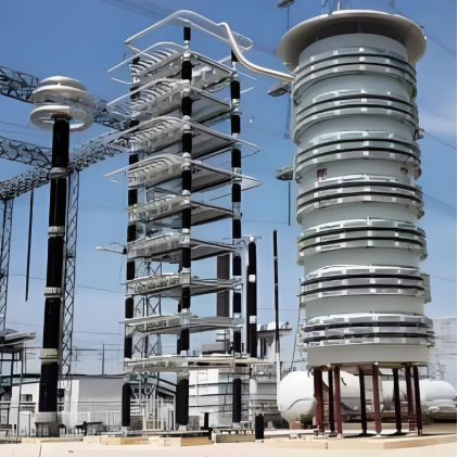
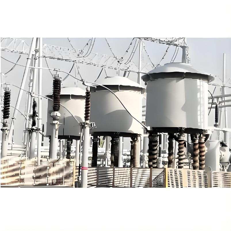
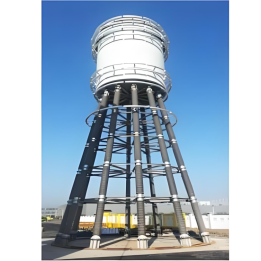
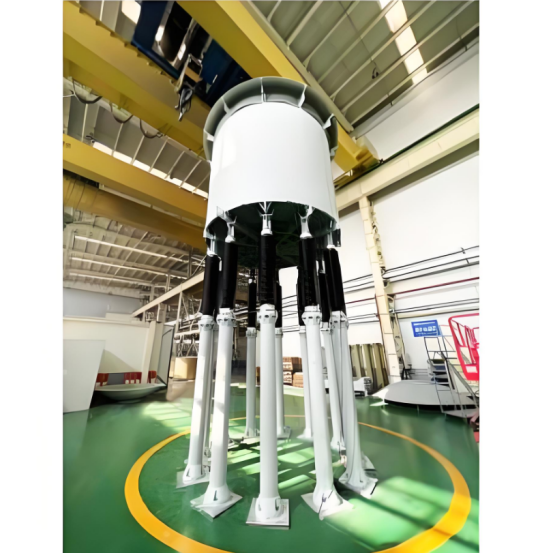
Line Traps are connected in series in high-voltage and ultra-highvoltage AC power lines to prevent excessive loss of carrier signals with frequencies generally in the 40-500KHz range under various conditions in the power system and to minimize interference from adjacent carriers.

Electrical schematic:

image.png

Parameters:

企业微信截图_1733207259661.png

What is the principle of shunt reactor voltage stabilization?

Voltage Stabilization Role:

  • The voltage in a power grid can fluctuate due to various factors, such as changes in load and line impedance. When the load is light, especially at the end of long transmission lines, the capacitive effect can cause the line to generate capacitive charging currents, leading to an increase in voltage.

  • A shunt reactor can absorb this excess capacitive reactive power, thereby reducing the magnitude of the voltage rise and stabilizing the grid voltage. It dynamically adjusts its reactive power output to regulate the grid voltage, keeping it within specified limits and ensuring the safe and stable operation of the power system.

Example:

  • In a high-voltage transmission line, without the regulation provided by a shunt reactor, the voltage at the end of the line might rise beyond the allowable range for equipment when the load is light, potentially damaging electrical devices. By installing a shunt reactor, the voltage rise can be effectively suppressed, ensuring the normal operation of the transmission line and user equipment.


Know your supplier
Wone
Main Categories
High voltage/Low voltage/Wire cable/Instrument meters/New energy/Tester/Production equipment/Generator/Electrical fittings/Integrated Electrical Equipment
Business Type
Design/Manufacture/Sales
Highest Annual Export (USD)
$50,000,000
Professional Experience
1 years
Workplace
65666m²m²
占位
占位
Related Products
Related Knowledges
What is Transformer Vector Groups?
Transformer Vector Group DefinitionThe transformer vector group denotes the phase difference between the primary and secondary sides of a transformer, while also defining the arrangement of high-voltage and low-voltage windings in three-phase transformers. Vector groups are determined by the connection configurations of three-phase transformers, which can be categorized into four main groups based on the phase difference between corresponding line voltages of the high-voltage and low-voltage sid
Edwiin
06/02/2025
What is a Pure Resistive AC Circuit?
Pure Resistive AC CircuitA circuit containing only a pure resistanceR(in ohms) in an AC system is defined as a Pure Resistive AC Circuit, devoid of inductance and capacitance. Alternating current and voltage in such a circuit oscillate bidirectionally, generating a sine wave (sinusoidal waveform). In this configuration, power is dissipated by the resistor, with voltage and current in perfect phase—both reaching their peak values simultaneously. As a passive component, the resistor neither
Edwiin
06/02/2025
What is a Pure Capacitor Circuit?
Pure Capacitor CircuitA circuit comprising only a pure capacitor with capacitanceC(measured in farads) is termed a Pure Capacitor Circuit. Capacitors store electrical energy within an electric field, a characteristic known ascapacitance(alternatively referred to as a "condenser"). Structurally, a capacitor consists of two conductive plates separated by a dielectric medium—common dielectric materials include glass, paper, mica, and oxide layers. In an ideal AC capacitor circuit, the current
Edwiin
06/02/2025
Resonant Frequency
Resonant Frequency
In a series circuit, the resonant frequency condition occurs when the inductive reactance equals the capacitive reactance. Changing the supply frequency alters the values of XL = 2πfL and XC = 1/2πfC.As the frequency increases, XL rises whileXC falls. Conversely, a decrease in frequency causesXL to drop andXCto rise.To achieve series resonance, the frequency is tuned to fr(pointP in the curve below), whereXL = XC.At series resonance, when XL = XCWhere frdenotes the resonant frequency in he
Edwiin
06/02/2025
Current Division and Voltage Division Rule
Current Division RuleA parallel circuit functions as a current divider, where the incoming current splits among all branches while the voltage across each branch remains constant. The Current Division Rule is used to determine the current through circuit impedances, as illustrated by the circuit below:The currentI splits intoI1 andI2 across two parallel branches with resistancesR1 andR2, whereVdenotes the voltage drop across both resistances. As is known,Then the equation of the current is writt
Edwiin
06/02/2025
Mesh Current Analysis Method
The Mesh Current Analysis Method is utilized to analyze and solve electrical networks with multiple sources or circuits comprising numerous meshes (loops) containing voltage or current sources. Also known as the Loop Current Method, this approach involves assuming a distinct current for each loop and determining the polarities of voltage drops across loop elements based on the assumed direction of the loop current.In mesh current analysis, the unknowns are the currents in different meshes, and t
Edwiin
06/02/2025
×
Inquiry
Download
Experts Electrical is dedicated to serving the personnel in the global power industry.
Join Experts Electrical, not only can you discover power equipment and power knowledge, but also canhnd like - minded friends!
商品视频播放