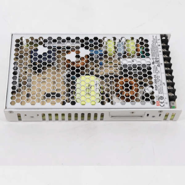
75-150W Mean Well DIN Rail Switching Power Supply for Industrial Control System
$80.00
Model
| Brand | Wone |
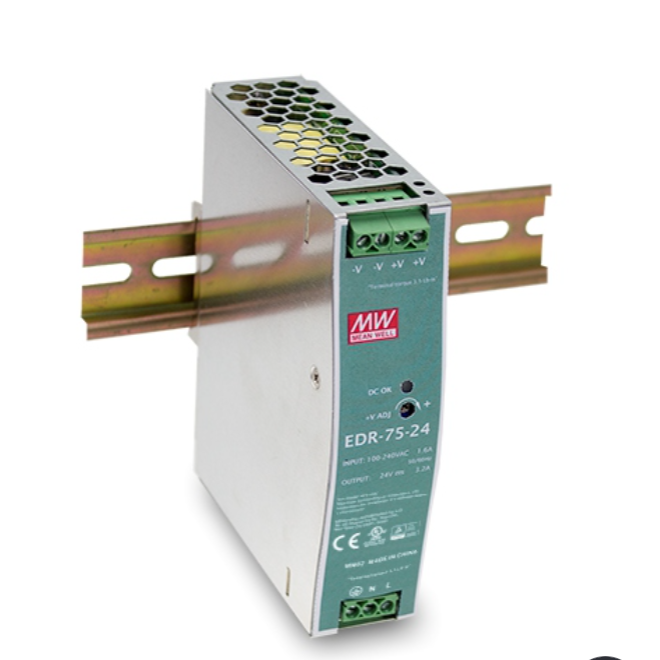
| Model NO. | EDR-75-24 3.2A 24V 75W Mean Well DIN Rail Switching Power Supply for Industrial Control System |
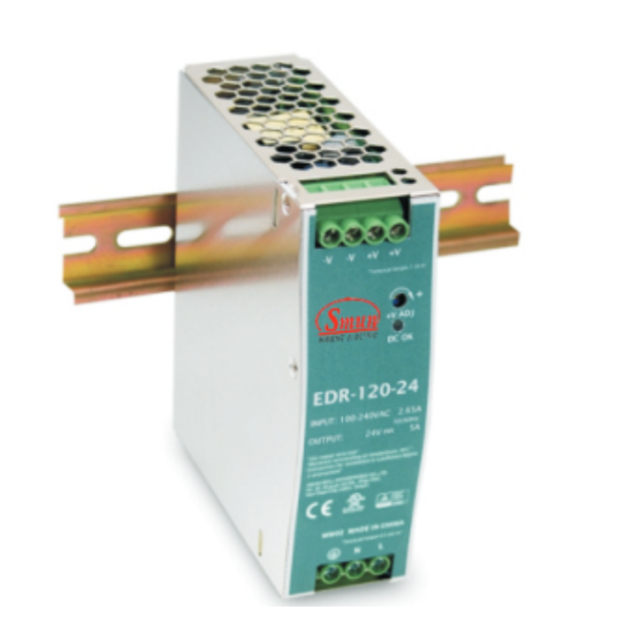
| Optional model | NDR-240-48 |
| current tolerance | 士1% |
| output | 0~5A |
| ripple and noise | 150mV |
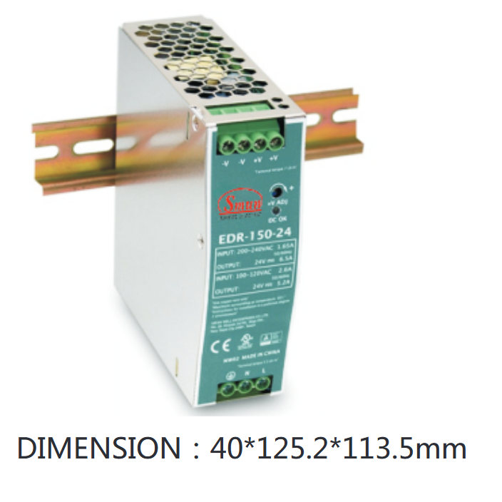
| size | 63*125*113.5mm |
| efficiency | 90% |
| Series | EDR-75 |
Feature
Wattage:75W-150W
Metal case, low cost
1∅, full range input
Slim size, model width: 32 - 40mm
EMC EN55022 class A
Assemble on industrial rail TS-35 / 7.5 or 15
2 years warranty
Specifications


Selection referance


Dimension
EDR-75/NDR-75

EDR-120/240/NDR-120

NDR-240