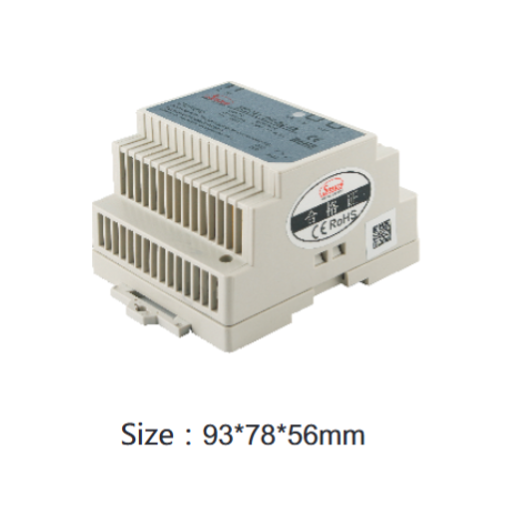
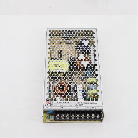
12-48V LED Screen AC/DC Power Supply
$40.00
Model
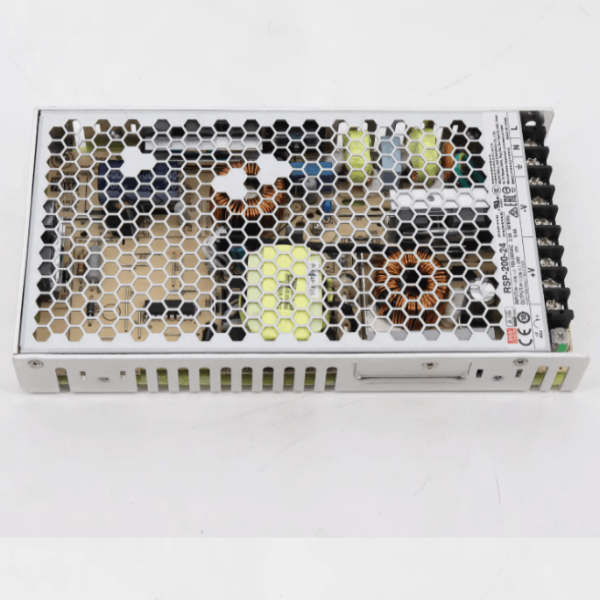
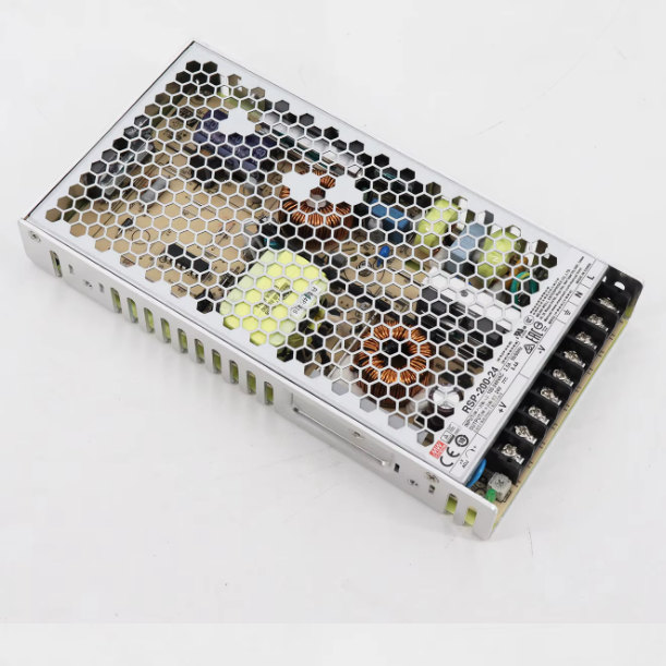
| Brand | Wone |
| Model NO. | RSP-200-24 LED Screen AC/DC Power Supply |
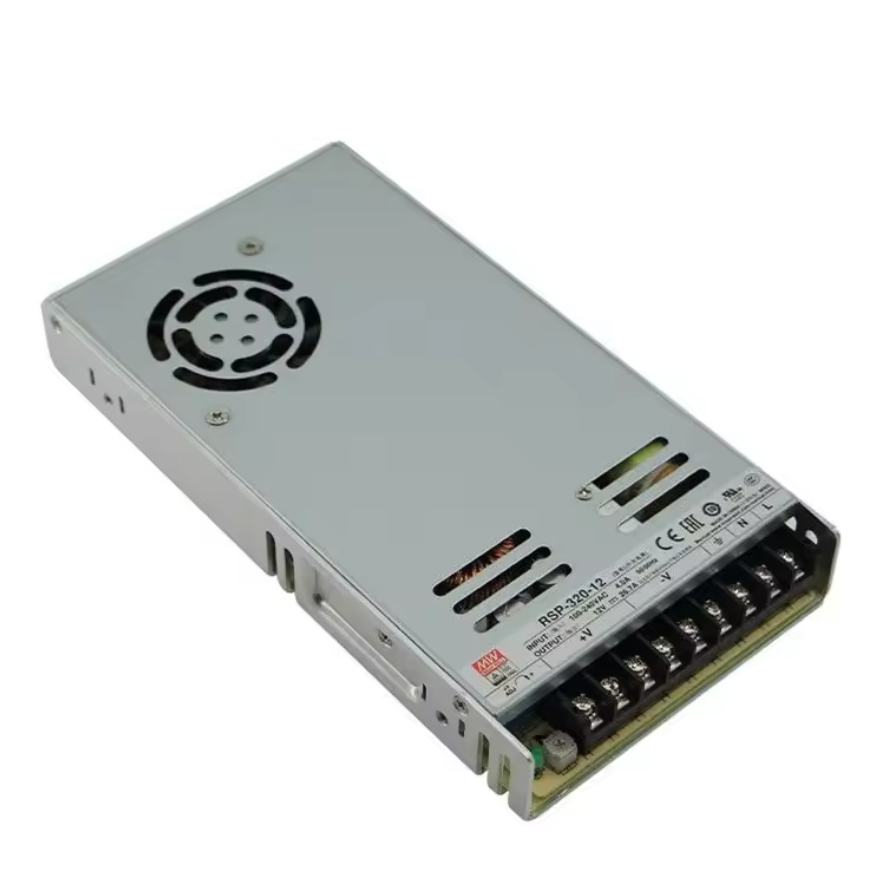
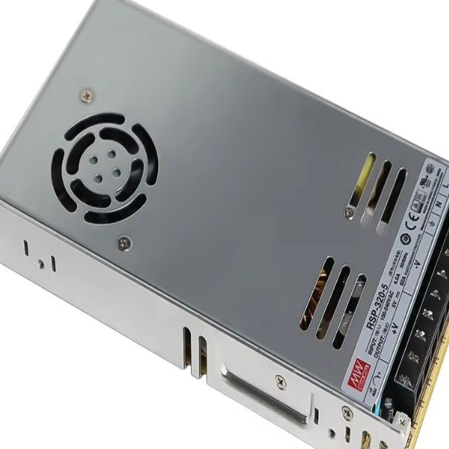
| Optional model | RSP-320-48 |
| current tolerance | 1% |
| output | 48V~6.7A |
| ripple and noise | 150mvp-p |
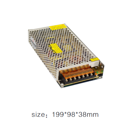
| size | 215*115*30mm |
| efficiency | 90% |
| Series | RSP-200/RSP-320 |
Feature
Universal full range AC input power
With active PFC function, PFC> 0.95
Protections:Short circuit/Overload/Over voltage/Over temperature
Cooling by free air convection
43,000 hours of continuous operation at 25 °
100% full load burn-in test
Efficiency up to 90%
years warranty
Selection referance


Dimension
RSP-200


RSP-320


Block Diagram

derating curve
RSP-200

RSP-320