| Brand | Wone |
| Model NO. | Monitor For Surge Arrester |
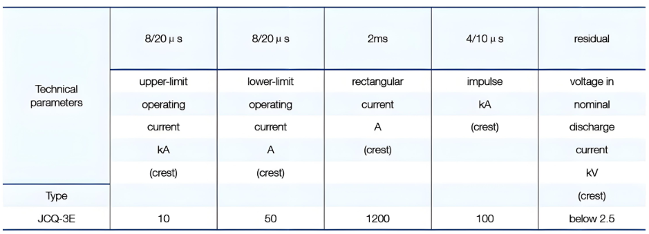
| Upper-limit operating current | 10kA |
| Lower-limit operating current | 50A |
| Series | Arrester Auxiliary Equipment |
Description:
JCQ-3E Lightning arrester monitor is connected in series with the arrester below, can be used to record the number of times a lightning arrester action, but also by a leakage current monitoring device milliammeter arrester at operating voltage. Lightning arrester for 220KV and below grade, site environmental conditions with the same lightning arrester is connected, it is not suitable for a serious pollution and severe shock place; the zinc oxide valve sheet, electrical properties are greatly enhanced.
Test procedure:
First charge the condenser by turning the megger. Cut off the charge circuit when it charges steadily on the condition that you keep the megger turning. Then make the condenser which has been charged well discharge the two terminals of the coil of the counter once, so the counter counts once. You should continue to make the experiment for ten times. The counter is good if it can operate normally and reliably every time. If not, it is possible that the counter can't work or its sensitivity is lower, it needs checking or repairing.
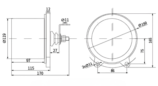
Structure and installation diagram
Conditions of using:
Suitable for indoor or outdoor.
Environmental temperature ( -40 - +40) ℃
The attitude does not exceed 2000m.
The power frequency (48 - 62) Hz.
No severe vibration place.
Structure and properties:
Electrical principle:
Lightning arrester monitor such as sampling valve plate, silicon bridge rectifier, a high-voltage capacitor, electromagnetic counter,milliammeter components. It is the use of the discharge current of the arrester, the valve plate (nonlinear resistor) the voltage generated by the silicon bridge rectifier, the charge on the capacitor, the discharge to the electromagnetic counter, every one record at a time, to achieve record lightning arrester action times.
This product uses the high quality stainless steel shell casing, has a good corrosion protection; the sealing performance is good, is not affected by the external environment. Internal element has good anti-aging properties, can be applicable to power system operation. JCQ-3E type lightning arrester monitor uses 2 bit digital display, the display is clear, easy to observe; is conducive to the short-term frequency by lightning arrester complete record.
The main technical performance:
Installation:
Install a counter with reference to its overall figure. The counter should be connected in series between the arrester and ground, in other words, it is connected in parallel with the flanges on the two terminals of insulating pedestal of an arrester. When you install a counter, you should scrape off the paint on the two fixture hole surface (4>11) which is on the flange of the counter first in order to en sure them being connected very well. And then fix the counter near the pedestal of an arrester by bolt of M10x40, which is a place where it is easy to be watched levelly It is also as an earthed terminal. Then connect the end of HV lead wire to the bus bar on the upper flange of insulation pedestal of an arrester by bolt of MI0x30. Check the counter after finishing installation and it mustn't be a clear incline. You must adjust it well with reference to the clause User should know that:, if the indicator of a counter does not point to “0”. Then it may be putted into operation. You shouldn't loose the M10 nut which is painted red and those six bolts of M6x20 on the pedestal in order to avoid destroying seal. The overall dimension and installation position of a counter are pointed in the following.
User should know that:
User should make a simple spot experiment in one counter before its being operated and after its operating for one or two years.
A simple way of testing the operation characteristic of a counter; You need one megger for 500V and one condenser for 600V 10 g F.
How does a surge arrester monitor work?
When the surge arrester is operating normally, the monitor continuously tracks its leakage current using a through-core sensor and displays the data on the corresponding interface. If an overvoltage event occurs in the system, the arrester activates to divert the resulting surge current into the ground. At this point, the current sensor in the monitor detects this change in current, triggering the counting unit to increment the operation count. The monitor then continues to track the leakage current after the arrester has operated, to determine whether the arrester has been damaged as a result of the operation.

