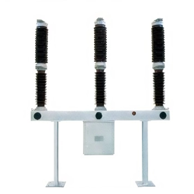
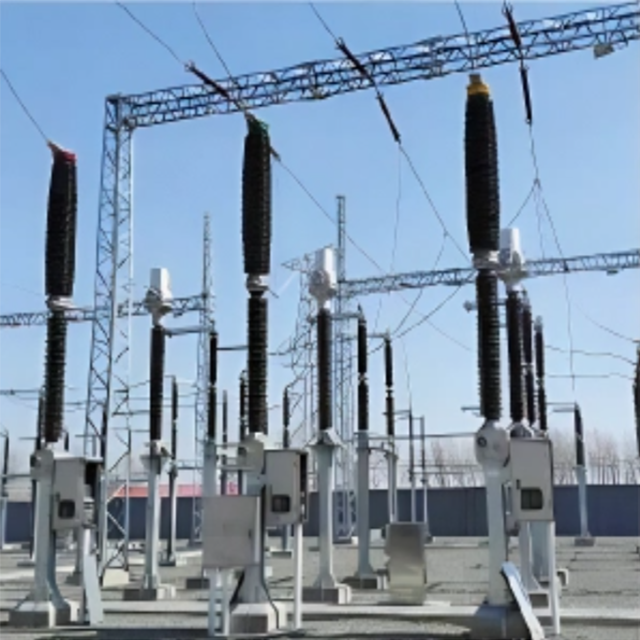
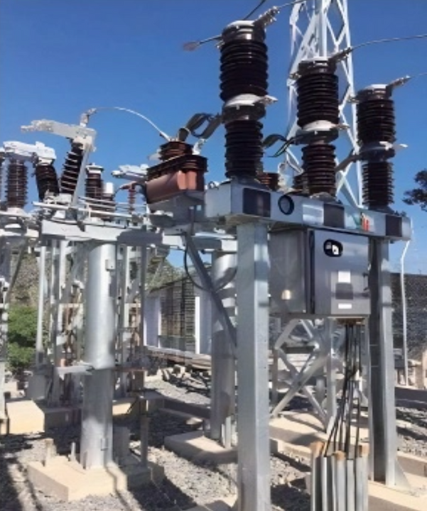
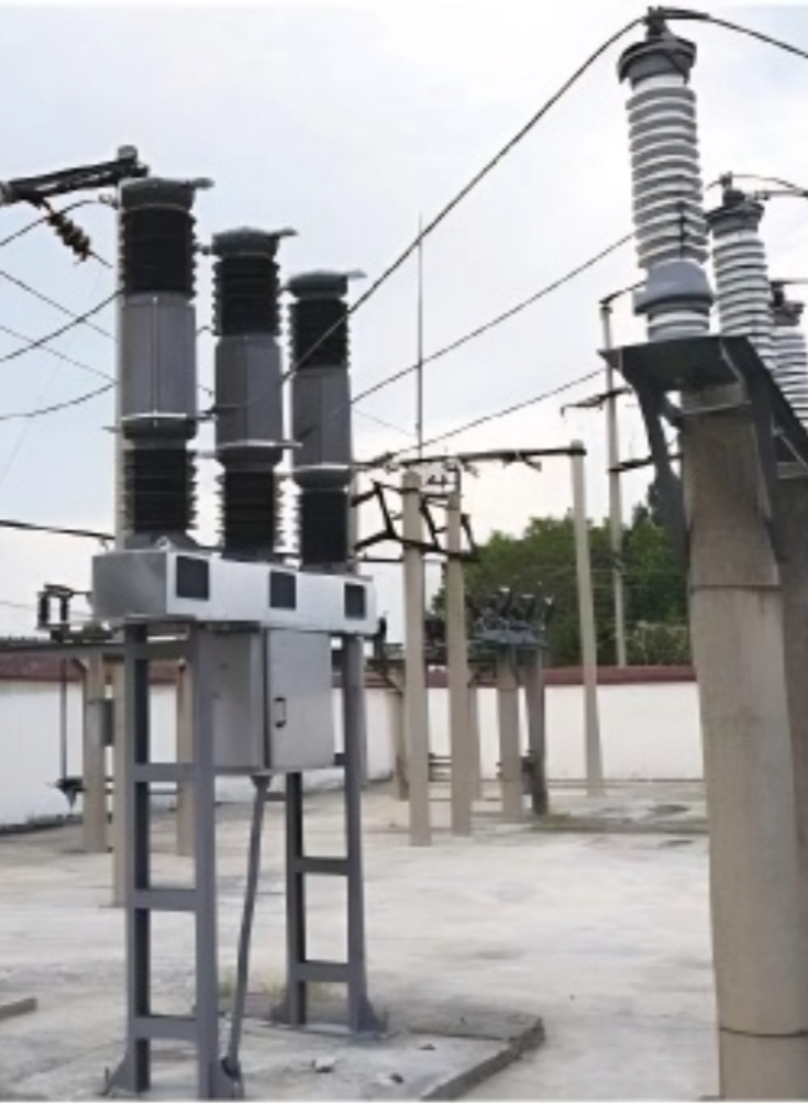
40.5kV HV Vacuum SF6 circuit breaker
discuss personally
Model
| Brand | Wone |
| Model NO. | 40.5kV HV Vacuum SF6 circuit breaker |
| Rated voltage | 40.5kV |
| Rated normal current | 2500A |
| Rated frequency | 50Hz |
| Rated short circuit breaking current | 31.5kA |
| Series | ZW39-40.5 |
Product introduction:
ZW39-40.5 vacuum circuit breaker is applicable in the 50Hz,40,5kV three-0hase electrical system and it is used forbreaking rated current, failure current or switching lines and realize the control and protection of electrical system,This product can be frequently operated and can also be used as a connection breaker.
Main characteristic:
The optimized choice of vacuum interrupter contact materials keeps the breaking interception value under 4A on average, effectively inhibiting operation overvoltage.
The circuit breaker has strong breaking capacity and the breaking short-circuit current 31.5kV can reach 30 times.
Equipped with CT34 improved spring operating mechanism, using cast aluminum base, good stability, mechanical life of more than 10000 times. Main features of CT34 improved structure (compared with original CT10A structure).
(a)The energy storage system adopts floating tooth structure. After closing, the remaining energy of the closing spring will continue to store energy and act as the closing buffer. There is no void, the energy storage time is short, and the energy storage can be in place within 8S;
(b)Operating mechanism adopts high strength cast aluminum frame, which has high strength, no welding stress and nigh anti-corrosion performance;
(c)The opening and closing spring and buffer are arranged in a centralized way, with compact structure and beautiful appearance;
(d)Imported Krupp NB52 grease is used for the mechanism, which is resistant to low temperature and not easy to harden, and is suitable for -50℃~+55°℃ area;
(e)The mechanism adopts oil buffer, small operation impact, small brake rebound.
This product can meet the environment requirements for a sea level of up to 3000m; with a high insulation level, the insulation level at broken sections reaches 118kV;
The circuit breaker may have internally or externally attached transformers. Four internally attached transformers can be attached to each phase of the circuit beaker and the iron core of the internally attached transformer adopts microcrystal alloy and magnetic material with high conductivity, and the electrical transformers above 200A can reach Grade 0.2 or Grade0.2S. The integrated structure of the circuit breaker is compact, and the binding techniques for the secondary windings of transformers have been fully optimized, which fully ensures that after binding the coils of the transformer has regular shape, free of burrs, and they will not become loosen at baking and not deformed after they are installed into the main unit, thus ensuring even electrical field.
The internally attached CT of the circuit breaker is compact, but due to the limited space inside the circuit breaker, it cannot realize very high accuracies (for example 0.2 or 0.2s. ) at small currents (such as those below 100A), and it also has small load. ln addition, the maintenance, capacity increase and replacement of internally attached current transformer is not convenient compared with those of the externally attached transformer.
In the space between the vacuum interrupter and the ceramic sleeve of this product is filled with SF6 gas (without internally attached CT: 0.02MPa, with internally attached CT: 0.2pa), ensuring that no internal condensation and moisture absorption will occur,
Imported products or products made by joint venture manufacturers were adopted for major secondary electric components, so they feature high reliability.
The surface treatments for the exposed parts of this product were al hot dip galvanized or directly use high quality stainless steel plates, which feature excellent corrosion resistance.
Main technical parameters:

Order notice :
Types and specifications of circuit breakers;
Rated electrical parameters (voltage, current and breaking current, etc.);
Ambient conditions (ambient temperatures, sea levels and grades of environmental pollution level);
Operating voltage and motor voltage of operating mechanism;
Number, current ratios, scale order combination and secondary load of internally or externally attached transformer;
Spare parts and specialized tools, names and quantity of equipment (need to be ordered separately).
How does a vacuum SF6 circuit breaker work?
Closing Process: When the operating mechanism receives a closing command, it drives the moving contact towards the stationary contact until they make contact and close tightly, thus completing the circuit. During the closing process, the contact pressure between the contacts must reach a certain value to ensure good electrical conductivity and mechanical stability, preventing issues such as overheating and loosening of the contacts during operation.
Opening Process: During the opening process, the operating mechanism rapidly moves the moving contact away from the stationary contact, creating an arc between the contacts. At this point, the insulating medium in the arc quenching chamber (such as sulfur hexafluoride gas) rapidly decomposes and ionizes under the high temperature of the arc, forming a plasma. The positive and negative ions in the plasma move in opposite directions under the influence of the electric field, causing the arc to cool and stretch, ultimately leading to its extinction and the disconnection of the circuit.