• DS4 40.5kV 126kV 145kV 252kV High voltage disconnect switch
DS4 40.5kV 126kV 145kV 252kV High voltage disconnect switch
discuss personally
Model
DS4-252/3150-50
DS4-252/2000-40
DS4-145/2000-40
DS4-126/3150-40
DS4-126/2000-40
DS4-72.5/2000-40
DS4-40.5/4000-50
DS4-40.5/2500-40
DS4-40.5/2000-40
Basic info
Brand ROCKWILL
Model NO. DS4 40.5kV 126kV 145kV 252kV High voltage disconnect switch
Rated voltage 252kV
Rated normal current 3150A
Series DS4
Product Detail

Description:

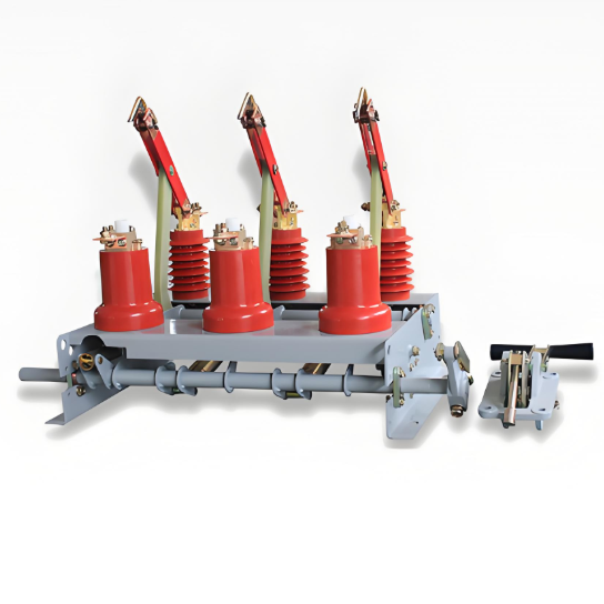
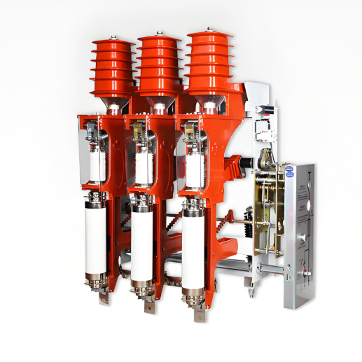
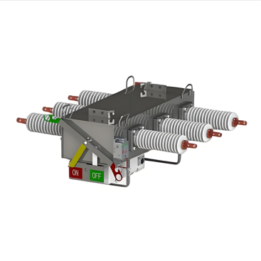
DS4 series disconnector adopts double column horizontal rotation structure, which is composed of three unipolar and operating mechanism. Each monopole consists of a base, a post insulator, and a conducting part. A rotating pillar insulator is installed at both ends of the base, and the contact arm and contact arm of the main electrical part are respectively fixed on the top of the pillar insulator. The operating mechanism drives one end of the pillar insulator to rotate, and drives the other end of the pillar insulator to reverse rotate 90° through the cross connecting rod, so that the conductive knife can turn on the horizontal plane to realize the isolation switch opening and closing. The opening state forms a horizontal insulation fracture.

Main Features:

  •  The conductive arm is made of rectangular aluminum alloy tube or aluminum alloy plate, high strength, light weight, large heat dissipation area, good anti-corrosion performance.

  •  The contact part of the conductive arm adopts external pressure plate spring structure. The plate spring is made of alloy material with good elasticity, which can keep the contact pressure stable for a long time and overcome the drawbacks of the spring internal pull structure.
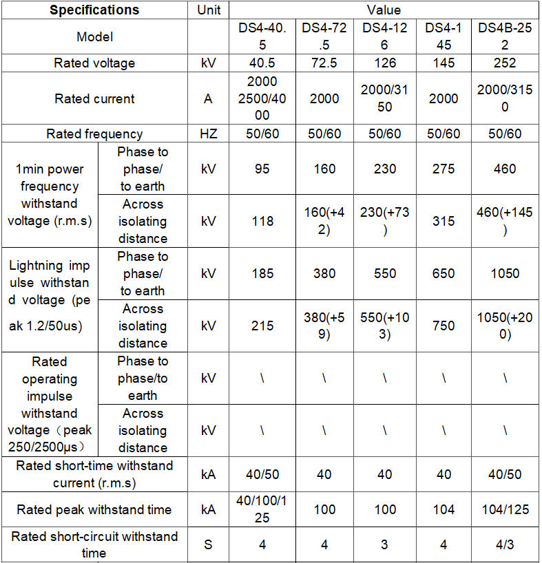
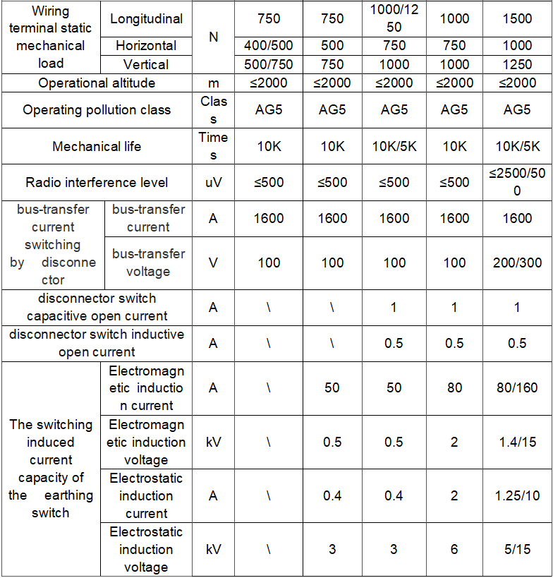
Technical parameter

What are the structural characteristics of the disconnector?
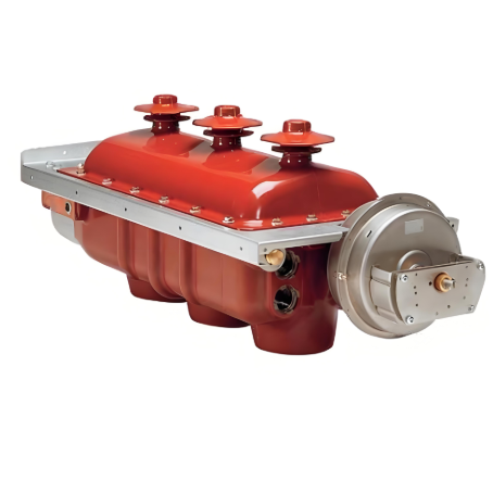
Contact System:

  • Description: The contact system is a critical part of the isolator switch, consisting of moving contacts and stationary contacts. The moving contact is typically connected to the operating handle via a transmission mechanism and can move to engage or disengage from the stationary contact under the influence of the operating force.

  • Surface Treatment: To ensure good contact performance, the contact surfaces are often specially treated, such as silver plating. This reduces contact resistance and minimizes heat generation.

  • Shape Design: The shape of the contacts is also important. Common types include knife-blade contacts and finger contacts, which provide a larger contact area to ensure safe and stable current flow.

Insulation Part:

  • Description: The insulation part ensures that there is sufficient insulation between different potential sections of the isolator switch. It is mainly composed of insulators, which are typically made of ceramic, glass, or composite materials.

  • Ceramic Insulators: Ceramic insulators have excellent insulation properties, mechanical strength, and weather resistance, making them suitable for various harsh environmental conditions.

  • Glass Insulators: Glass insulators have good self-cleaning properties, reducing the impact of dust and dirt on insulation performance.

  • Composite Insulators: Composite insulators are lightweight and have excellent pollution flashover resistance, making them advantageous in special application scenarios.

Transmission Mechanism:

  • Description: The transmission mechanism is used to transfer the operating force from the operating handle to the moving contact, enabling the opening and closing actions of the contacts. It can be a manual linkage mechanism or an electric operating mechanism.

  • Manual Linkage Mechanism: This type of mechanism is simple in structure and highly reliable. It converts the rotational motion of the operating handle into linear or rotational motion of the moving contact through a series of linkages and shafts.

  • Electric Operating Mechanism: Suitable for applications requiring remote control or frequent operation, this mechanism uses a motor, reduction gear, and transmission components to achieve automated operation of the isolator switch.

Base and Support:

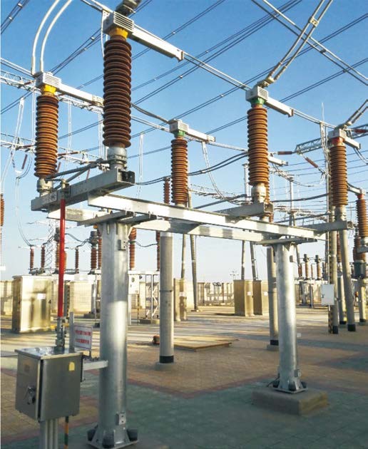
  • Description: The base and support are the supporting structures of the isolator switch, used to fix the contact system, insulation part, and transmission mechanism. The base is usually made of metal and has sufficient mechanical strength and stability to bear the weight of the isolator switch and various forces generated during operation.

  • Design Considerations: The support is designed based on the installation method and application scenario of the isolator switch. For example, the support structure of indoor isolator switches differs from that of outdoor isolator switches. Outdoor isolator switches require supports that consider factors such as wind resistance, rain protection, and corrosion resistance.


Know your supplier
ROCKWILL
Rockwill Electric Group Global Manufacturer of High voltage and medium-voltage power equipment and smart grid solutions. Headquartered in Wenzhou, China. Serving 100+ countries with quality, innovation, and trust. What We Offer: • HV-MV switchgear (VCB, SF₆ circuit breakers, RMU, GIS) • Distribution transformers and substations • Smart grid and monitoring systems • Solar, wind, EV charging, and energy storage solutions • EPC turnkey power projects Certified: ISO 9001 / ISO 14001 / ISO 45001
Main Categories
High voltage
Business Type
Design/Manufacture/Sales
Highest Annual Export (USD)
$150,000,000
Professional Experience
16 years
Workplace
108000m²m²
占位
占位
Related Products
Related Knowledges
Impact Analysis of Voltage Transformer Installation on Line Side vs. Load Side of Power Inlet Circuit Breaker for (ATS)
Automatic backup switching (ABTS) devices are core components ensuring the safe, reliable, and stable operation of factory power grids. Their startup logic strictly follows the dual criteria of "loss of voltage in the working power supply + no - current detection", effectively avoiding misjudgments caused by secondary disconnection of voltage transformers (VTs) or maloperations of ABTS due to secondary circuit faults of current transformers (CTs). The activation condition requires both "no volta
James
07/03/2025
What tests need to be done on voltage transformers?
Practical Experience Sharing from an Electrical Engineer in the FieldBy Oliver, 8 Years in the Electrical IndustryHi everyone, I'm Oliver, and I've been working in the electrical industry for 8 years.From early involvement in substation commissioning and equipment inspection, to now managing the maintenance and fault analysis of entire power systems, one of the most frequently encountered devices in my work has been the voltage transformer (VT / PT).Recently, a friend who's just starting out ask
Oliver Watts
07/03/2025
What are the development trends of voltage transformers?
By Echo, 12 Years in the Electrical IndustryHi everyone, I'm Echo, and I've been working in the electrical industry for 12 years.From early involvement in commissioning and maintenance of distribution rooms to later participation in electrical system design and equipment selection for large-scale projects, I’ve witnessed how voltage transformers have evolved — from traditional analog devices to intelligent, digital components.The other day, a new colleague from a power company asked
Echo
07/02/2025
Design of Electromagnetic Compatibility Performance for Electronic Voltage Transformers
With the rapid development of power systems, electronic voltage transformers (EVTs), as key measurement devices in power systems, their performance stability and reliability are crucial for the safe and stable operation of power systems. The electromagnetic compatibility (EMC) performance, as one of the core indicators of EVTs, is directly related to the ability of the device to work normally in complex electromagnetic environments and whether it will cause electromagnetic interference to other
Dyson
07/02/2025
Case Analysis of Abnormal Secondary Circuits in Voltage Transformers
1. Fault SituationIn September 2023, as a front - line fault maintenance worker, I detected abnormal voltage on the 10kV Section I bus of a substation during monitoring duty and informed the operation and maintenance team. The monitoring system showed: U0 = 0 kV, Ua = 6.06 kV, Ub = 5.93 kV, Uc = 6.05 kV, Uab = 10.05 kV, Ubc = 5.94 kVMy team and I rushed to the site. We suspected the secondary air circuit breaker of the 10kV Section I bus voltage transformer was closed and found the U - phase fus
Felix Spark
07/02/2025
What are the causes of failure of ferromagnetic voltage transformers in new energy power stations?
By Felix, 15 Years in the Electrical IndustryHi everyone, I'm Felix, and I've been working in the electrical industry for 15 years.From early involvement in traditional substation commissioning and maintenance to now managing electrical system operations for multiple photovoltaic and wind power projects, one of the most frequently encountered devices I deal with is the Electromagnetic Voltage Transformer (PT).The other day, a shift operator at a new energy plant asked me:“We have an electr
Felix Spark
07/02/2025
×
Inquiry
Download
Experts Electrical is dedicated to serving the personnel in the global power industry.
Join Experts Electrical, not only can you discover power equipment and power knowledge, but also canhnd like - minded friends!