With the rapid development of power systems, electronic voltage transformers (EVTs), as key measurement devices in power systems, their performance stability and reliability are crucial for the safe and stable operation of power systems. The electromagnetic compatibility (EMC) performance, as one of the core indicators of EVTs, is directly related to the ability of the device to work normally in complex electromagnetic environments and whether it will cause electromagnetic interference to other devices. Conducting in - depth research and design on the EMC performance of EVTs is of great significance for improving the overall stability and safety of power systems.
1 Overview of Electromagnetic Compatibility Performance of Electronic Voltage Transformers
1.1 Definition and Requirements of Electromagnetic Compatibility
Electromagnetic compatibility (EMC) refers to the ability of a device or system to work normally without interference in a specific electromagnetic environment and not cause unbearable electromagnetic harassment to other things in the environment. For EVTs, they need to maintain stable measurement performance in complex electromagnetic environments and not cause electromagnetic interference to other devices. Therefore, during the design and manufacturing stages of EVTs, the EMC performance must be considered, and corresponding safeguard measures must be formulated.
1.2 Working Principle of Electronic Voltage Transformers
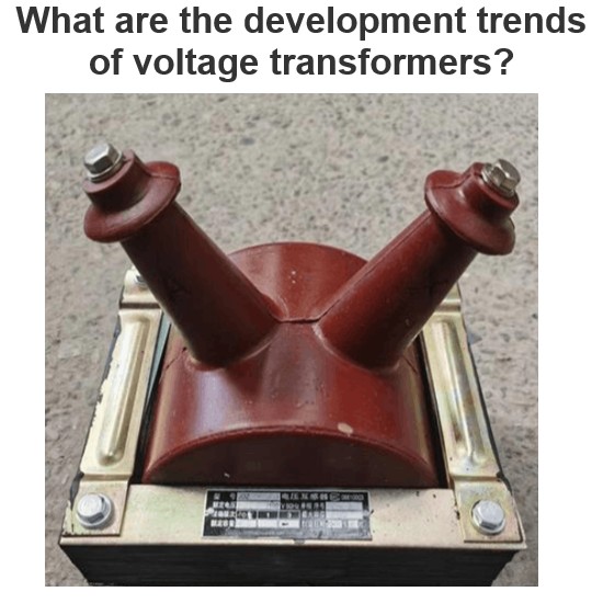
EVTs use the principle of electromagnetic induction and high - precision electronic measurement technology to convert high - voltage signals in power systems into low - voltage signals. They usually consist of a primary sensor, a secondary conversion circuit, and a signal processing unit. The primary sensor is responsible for converting high - voltage signals into weak current/voltage signals proportional to the primary voltage; the secondary conversion circuit further converts the weak signals into standard digital/analog signals; the signal processing unit improves the accuracy and stability of measurement through operations such as filtering, amplifying, and calibrating. EVTs can cover various forms, such as electronic voltage transformers for measuring single - channel/multi - channel voltages, electronic current transformers for measuring single - channel/multi - channel currents, or integrated transformers as shown in Figure 1 that measure one - way voltage, current, and corresponding power simultaneously.

1.3 Analysis of Electromagnetic Harassment and Electromagnetic Sensitivity
EVTs are vulnerable to external electromagnetic harassment in the electromagnetic environment, such as lightning strikes and transient overvoltages from switch operations, which can cause problems such as increased measurement errors and unstable data; at the same time, the high - frequency harmonics and electromagnetic radiation generated by EVTs themselves can also interfere with other electrical equipment. Therefore, when designing EVTs, the issues of electromagnetic harassment and electromagnetic sensitivity need to be fully considered, and suppression and protection measures should be taken .
The EMC performance test of EVTs is a key link to ensure their stability and accuracy in actual operation. It focuses on the anti - interference ability and classifies the evaluation standards into Class A and Class B according to the severity of the test results:
2 Analysis of Electromagnetic Compatibility Performance Tests of Electronic Voltage Transformers
2.1 Test Content and Evaluation Standards
- Class A: It requires that when EVTs are subjected to electromagnetic harassment, the measurement accuracy remains within the specification limits, and the output voltage signal is consistent with the actual value without affecting the monitoring and control of the power system.
- Class B: It allows a temporary decline in the measurement performance (the part not related to protection) of EVTs, but it must not affect the execution of protection functions, and the equipment does not need to be reset/restarted; the output voltage must be controlled within 500V to avoid interfering with the power system.
2.2 Conducted Interference Tests
Conducted interference propagates through conductive paths such as wires and metal pipes and is one of the main types of electromagnetic harassment faced by EVTs. It includes two types of tests:
- Electrical Fast Transient/Burst Test: Simulates the transient harassment (with a wide frequency spectrum) when inductive loads such as relays and contactors are disconnected. Applies a fast - transient burst to the EVT, observes the stability and accuracy of the output voltage signal, and evaluates the anti - interference ability.
- Surge (Impact) Immunity Test: Simulates transient overvoltages/overcurrents caused by switch operations and lightning strikes (with large energy and short duration). Applies a surge voltage of a certain amplitude to the EVT to test the equipment's withstand capacity and performance stability.
2.3 Radiated Interference Tests
It includes four types of tests to simulate interferences in different electromagnetic environments:
- Power Frequency Magnetic Field Immunity Test: Applies a power frequency magnetic field of a certain intensity to the EVT, observes the stability and accuracy of the output voltage signal, and evaluates the anti - interference ability in the power frequency magnetic field environment.
- Damped Oscillatory Magnetic Field Immunity Test: Simulates the damped oscillatory magnetic field (with fast attenuation and high frequency) generated when the disconnector in a high - voltage substation switches the bus. Applies the corresponding magnetic field to the EVT to test the stability of the measurement performance.
- Pulse Magnetic Field Immunity Test: Simulates the pulse magnetic field (with fast rise and high peak value) generated by lightning strikes on metal components. Applies a pulse magnetic field to the EVT to verify whether the insulation performance and measurement accuracy of the equipment are affected.
- Radio Frequency Radiated Electromagnetic Field Immunity Test: Simulates parasitic radiation from industrial electromagnetic sources, radio broadcasts/mobile communication base stations, etc. Applies a radio frequency electromagnetic field of a certain intensity to the EVT, observes the stability of the output signal, and evaluates the anti - interference ability.
3 Design Principles for Electromagnetic Compatibility of Electronic Voltage Transformers
3.1 Circuit Design Principles
- Floating Ground Design: Adopt floating ground technology to insulate the circuit signal lines from the chassis, block the coupling of interference currents on the chassis to the signal circuit, reduce noise, and improve signal accuracy and stability.
- Reasonable Wiring Layout: Optimize the layout of power supplies, grounds, and signal lines. Reduce the parallel distribution of lines and minimize the coupling interference between lines through methods such as layered wiring and orthogonal wiring.
- Filter Capacitor Design: Configure filter capacitors at the input end of the module power supply. Select the capacitors based on factors such as capacitance value, voltage resistance, and frequency characteristics to filter out high - frequency noise and interference introduced by the power supply.
- Low - level Logic Design: Give priority to low - level logic devices (such as 3.3V level devices) to avoid unnecessary high logic levels, reduce circuit power consumption and the generation of high - frequency interference.
- Rise/Fall Time Control: Select the slowest rise/fall time allowed by the circuit function to suppress unnecessary high - frequency components, reduce high - frequency noise in the circuit, and improve signal stability and accuracy.
3.2 Internal Structure Design Principles
- Fully Enclosed Shielding Structure: The chassis shell adopts a fully enclosed shielding design to ensure good contact and grounding of each surface, effectively block external electromagnetic field interference, and protect the internal electronic circuits.
- Minimization of Exposed Wiring: Shorten the length of exposed wiring in the chassis by optimizing the layout and reasonably arranging components to reduce electromagnetic radiation and coupling interference.
- Group Bundling of Wires: Bundle wires according to signal types (separate digital signals and analog signals), and keep a certain distance to reduce the mutual influence between wires and improve signal clarity and accuracy.
- Conductive Adhesive Bonding: Use conductive adhesive for bonding at the chassis interface to ensure electrical connection and shielding effect, reduce contact resistance, and improve shielding efficiency.
4 Strategies for Improving Electromagnetic Compatibility Performance of Electronic Voltage Transformers
4.1 Anti - interference Design of Power Ports
- Install Power Filters: Select suitable power filters according to the rated power and working environment of the EVT, and install them close to the power inlet to filter out high - frequency noise and transient pulses and ensure power purity.
- Adopt Redundant Power Design: Configure multiple power modules. When a single module fails, the remaining modules quickly take over the power supply, improving the power supply reliability, anti - interference ability, and overall stability of the EVT.
- Strengthen Shielding and Grounding of Power Lines: Use shielded cables to wrap power lines to reduce electromagnetic radiation and coupling; ensure good grounding of the lines, introduce interference currents into the ground, and avoid damaging the EVT.
4.2 Electrostatic Discharge Protection of Signal Ports
- Install Transient Harassment Absorption Devices: Select suitable transient voltage suppression diodes (TVS), varistors, and other devices. These devices can quickly absorb energy during electrostatic discharge, control the voltage within a safe range, and protect internal electronic components.
- Adopt Differential Signal Transmission Method: Divide the signal into positive and negative channels for differential transmission. Use the signal difference between channels to extract effective information, resist common - mode interference, improve signal transmission quality, and reduce the interference of electrostatic discharge.
4.3 Optimization of Chassis Shielding Performance
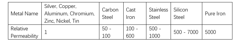
- Select High - Permeability Materials: Give priority to materials with high magnetic permeability such as iron plates to make the chassis, enhance the magnetic field shielding ability, absorb and disperse magnetic field energy, and reduce interference to the inside of the EVT (the relative magnetic permeability of metals is shown in Table 1).
- Optimize Chassis Structure Design: Adopt a fully enclosed shielding structure to ensure good contact and grounding of each surface of the chassis and enhance the shielding effect.
- Strengthen Chassis Grounding Treatment: Ensure a reliable grounding connection between the chassis and the ground, introduce interference currents into the ground, and improve shielding efficiency.
5 Conclusion
This paper conducts in - depth research on the EMC performance of EVTs, proposes principles from the aspects of circuit design and internal structure design, and formulates strategies such as anti - interference design of power ports, electrostatic protection of signal ports, and optimization of chassis shielding. The aim is to improve the anti - interference ability and stability of EVTs in complex electromagnetic environments, ensure their accurate and reliable measurement of voltage signals in power systems, and lay a solid foundation for the safe and stable operation of power systems.