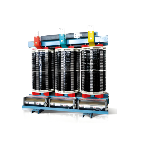
| Brand | Vziman |
| Model NO. | 33kv Epoxy Cast Dry Distribution Transformer |
| Rated capacity | 1000kVA |
| Series | Dry Distribution Transformer |
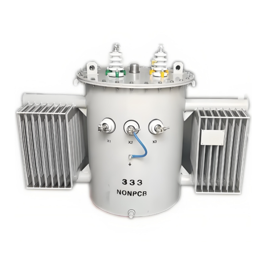
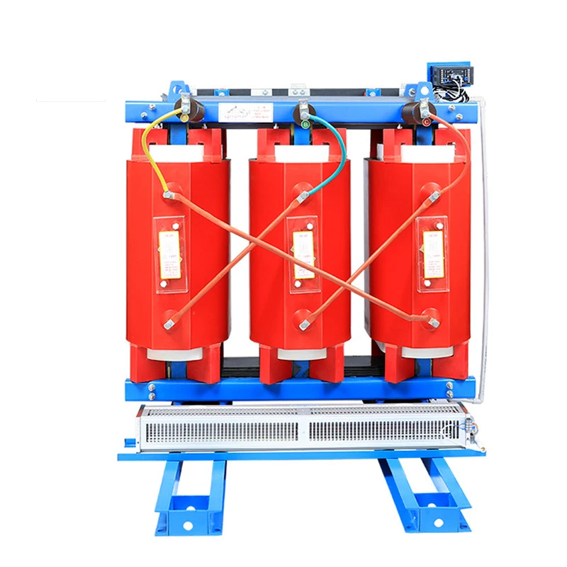
Product overview:
Lower loss, more energy saving, 35% energy saving than SCB11 transformer loss.
Actual measurement is better than GB and IEC standards, CB, CCC, KEMA SASO and other certification.
Better safety excellent fire performance, F1 class.
High lightning resistance level (175kV for 33kV products).
Equipped with perfect temperature protection control system, it can operate at 120% rated load under forced air cooling condition.
Global operation verified high reliability, has been exported to more than 50 countries and regions.
Mainly used in 33KV urban distribution network, industrial and mining enterprises and civil building power supply and distribution system.
5793 sets of products have been successfully sold to Uganda, Ethiopia, Tanzania, Zimbabwe, Ghana, South Africa, Kenya, Zambia, Rwanda and other countries.
Implementation standard: IEC 60076 series, GB1094 series, GB/T6451-2008.
The shell material is aluminum alloy, cold rolled steel plate, stainless steel, etc. (protection grade IP20, IP23, etc.
Product advantages
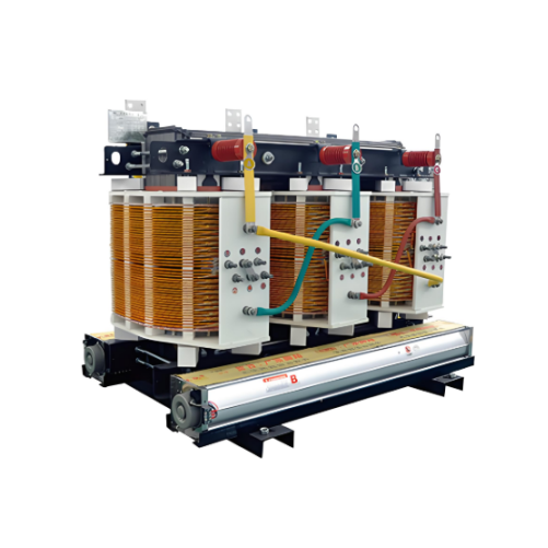
Leading technology
High pressure copper tape winding technology, flame retardant formula vacuum pouring.
Low pressure copper foil winding technology, thermosetting epoxy prepreg cloth insulation.
High quality iron core 45° full oblique joint step laminated structure .
The iron core
The core is made of high quality cold rolled grain oriented silicon steel sheet insulated by mineral oxide.
Minimize loss level, no-load current and noise by controlling the cutting and stacking process of silicon steel sheet.
Apply class F or CLASS H core paint on the surface of assembled cores to prevent corrosion and rust.
Low voltage winding
The low voltage winding is made of high quality copper foil.
Insulated by thermosetting epoxy preimpregnated cloth.
Winding ends are insulated with thermosetting epoxy preimpregnated cloth.
Excellent insulation resistance.
Very good resistance to radial stress caused by short circuit.
The outgoing terminal of the low-voltage winding is tinned copper bar.
The whole winding is heated in the oven to 140°C and polymerized for 4 hours. It has excellent corrosion resistance of industrial gas.
High voltage winding
Made of insulated copper wire and using the patented technology of Hengfengyou Electric.
For small volume products, the high voltage winding uses a linear voltage gradient from top to bottom.
For products with large capacity, the high voltage winding is made by "tape winding" technology.
The application of these methods makes the electric field between adjacent conductors very low.
Transformer structure is reliable during normal operation and transportation.
High quality material
Baowu Steel Group production of silicon steel sheet.
China produces high quality anaerobic copper.
Huntsman Epoxy resin (including flame retardant filler).
Product parameters

Ordering instructions:
Main parameters of transformer (voltage, capacity, loss and other main parameters.
Transformer operating environment (altitude, temperature, humidity, location, etc.
Other customization requirements (coupling groups, colors, oil pillows, etc.
The minimum order quantity is 1 sets, worldwide delivery within 7 days.
Normal delivery period of 30 days, worldwide fast delivery.
How the core of a transformer is made?
Material Selection:
Silicon Steel Sheets: The most commonly used core material is silicon steel sheets, as they possess low losses, high magnetic permeability, and good mechanical properties. The silicon content in silicon steel sheets usually ranges from 2% to 4.5%. The higher the silicon content, the lower the magnetic losses.
Amorphous Alloys: In some high-performance transformers, amorphous alloys are also used as core materials. Amorphous alloys have even lower magnetic losses and higher magnetic permeability.
Material Preparation:
Cutting: Cut the silicon steel sheets or amorphous alloy materials into the required sizes according to the design requirements. Usually, shearing machines or laser cutting machines are used for cutting to ensure that the edges are neat and free of burrs.
Cleaning: Clean the cut silicon steel sheets to remove the oil stains and impurities on the surface and ensure that the surface is clean.
Annealing: Anneal the cleaned silicon steel sheets to eliminate internal stresses and improve magnetic properties.
Lamination:
Lamination Methods: Silicon steel sheets are usually laminated in an interleaved or straight lamination manner.
Interleaved Lamination: Interleave the silicon steel sheets to reduce the air gaps in the magnetic circuit and improve the magnetic permeability.
Straight Lamination: Stack the silicon steel sheets directly, which is suitable for small transformers.
Lamination Tools: Use specialized lamination tools (such as laminating machines) for lamination to ensure the flatness and tightness of the silicon steel sheets.
Fixing: During the lamination process, use clamps or straps to fix the silicon steel sheets to prevent displacement during subsequent processing.
Assembly:
Core Columns: Assemble the laminated silicon steel sheets into core columns. The shape and size of the core columns are determined according to the design requirements of the transformer.
Yokes: Connect the core columns through yokes to form a closed magnetic circuit. The function of the yokes is to guide the magnetic flux and reduce magnetic leakage.
Fastening: Use bolts, nuts or other fasteners to fix the core columns and yokes together to ensure the mechanical strength of the core.
Insulation Treatment:
Painting: Coat the surface of the core with insulating paint to improve the insulation performance of the core and reduce eddy current losses.
Insulation Paper: Insert insulation paper between the core columns and yokes to ensure insulation between each part.