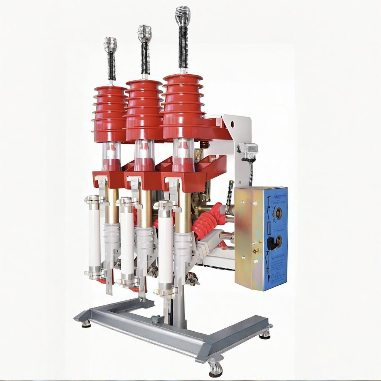
Short-Circuit Fault Analysis of 10kV Puffer-Type Load Switch

Felix Spark
06/28/2025

1. Fault Overview
In June 2013, a fault occurred in a high - voltage switchgear in operation in a certain urban area, causing a 10kV line to trip. On - site investigation revealed that the faulty switchgear was a pneumatic ring - network high - voltage load switchgear (HXGN2 - 10 type), and the fault characteristic was a three - phase arc short circuit. After isolating the fault and restoring power supply to users, it should be noted that the same type of switchgear in this area, which was put into operation between 1999 and 2000 (with an operation period of more than 12 years, a designed rated current of 630A, and an actual operating current mostly ≤ 300A), has experienced similar faults many times, posing a threat to the reliable operation of the power grid.
2. Working Principle of Pneumatic Load Switches
The pneumatic ring - network cabinet is named for being equipped with a pneumatic load switch. Its movable contact rod also functions as an air cylinder —— the hollow structure contains a sealed “piston”, which is driven by the main shaft to realize the linear movement of closing and opening. When opening, the piston quickly compresses the air in the movable contact rod (air cylinder), and the compressed air is blown towards the arc generated by the separation of the arc - extinguishing contacts through the arc - resistant plastic nozzle at the top, extinguishing the arc by stretching it; the high - speed air flow quickly restores the insulation strength of the medium at the break, preventing the arc from reigniting.
Due to the limited ability of the switch to break fault currents (only applicable to systems below 35kV ), a design scheme of “separating the conductive element from the arc - igniting element” is adopted:
  • Conductive element: Red copper plum - shaped contact fingers + conductive rod, responsible for current transmission;
  • Arc - igniting element: Copper - tungsten alloy arc - igniting rod + arc - igniting ring, specially for arc ignition and extinction.
When opening, the outer surface of the movable contact rod first separates from the static contact fingers, and then the arc - igniting ring separates from the arc - igniting rod. The arc is restricted to burn between the arc - igniting components, avoiding damage to the main contacts; the movable contact rod and the lower terminal are connected by plum - shaped contact fingers to ensure electrical conduction.
3. In - depth Analysis of Fault Causes
(1) Preliminary Investigation (External Factors)
The designed rated current of this type of switch is 630A, but the dispatching data shows that the operating current of the outgoing switch of the substation is 283A, and the theoretical current passing through the switchgear on the way is ≤ 283A. Combined with the on - site environment (sunny weather, no pollution on the cabinet body), external factors such as over - current, over - voltage, and pollution flashover can be directly excluded, and the fault is attributed to the defects of the switchgear itself.
(2) Disassembly and Test Verification
After disassembling the faulty cabinet, it is initially speculated that “poor contact between the movable and static contacts leads to overheating and burning”, but a definite conclusion cannot be drawn due to severe damage to the cabinet. Therefore, sampling detection is carried out on the same type of switchgear in operation:
  • Withstand voltage and loop resistance: The withstand voltage level is qualified, and the loop resistance is 114μΩ (complying with technical regulations );
  • Temperature rise test: The 30 - minute current - rising test data (Table 1 ) shows that the temperature rise reaches 84.2℃ at 400A and as high as 133.1℃ at 630A, far exceeding the national standard for stable judgment of “temperature rise ≤ 1K within 1 hour or ≤ 2K within 3 hours”.

(3) Identification of Root Causes
Comprehensive testing and structural analysis show that the fault originates from the failure of the contact system, specifically manifested as:
  • Insufficient spring force: It cannot effectively contract the plum - shaped contact fingers, resulting in the deterioration of the “surface contact” between the contact fingers and the movable contact rod into “line contact”, and a sharp reduction in the contact area;
  • Defects in processing precision: Insufficient precision in the arc surface/planar processing of the plum - shaped contact fingers aggravates poor contact;
  • Oxidation vicious cycle: The contact fingers and the movable contact rod are exposed to the air, and oxidation leads to an increase in contact resistance → increased heating → further attenuation of spring tension → worse contact effect, eventually causing air ionization arc short circuit and line tripping.
4. Equipment Transformation and Optimization Solutions
(1) Process Upgrade: Precise Control of Contact Quality
Aiming at the core problem of “poor contact”, improvements are made from the material and processing ends:
  • Spring selection: Adopt springs with high fatigue resistance to ensure stable spring force within the design life (including the condition of making and breaking the rated current ), avoiding contact problems caused by spring failure;
  • Contact finger processing: Strictly control the processing precision of the arc surface and plane of the plum - shaped contact fingers to ensure complete fitting with the cylindrical arc surface of the movable contact rod, eliminating the hidden dangers of line contact/point contact, and ensuring the current - carrying capacity and temperature rise compliance of the contacts.
(2) Design Optimization: Full - process Condition Monitoring
Integrate the “online monitoring” function into the cabinet structure design to realize visual status:
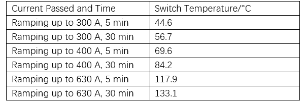
  • Temperature measurement window and probe: Set up a convenient temperature measurement window, install a temperature probe at the static contact, and display the temperature of the contact part inside the cabinet in real - time through the panel instrument;
  • Data storage and early warning: Configure storage equipment to record operating data. Even if the equipment ages, abnormal situations can be identified in advance through data analysis, triggering the replacement and maintenance process, shifting from passive repair to active operation and maintenance.
(3) Operation and Maintenance Strengthening: Dynamic Defect Treatment
For the equipment in operation, optimize the operation and maintenance methods:
  • Observation window transformation: Change the fixed observation window to a movable one to facilitate temperature monitoring inside the cabinet;
  • Normalization of partial discharge testing: Carry out partial discharge testing of the switchgear during peak load periods to capture insulation defects in advance and avoid the expansion of faults.
5. Application Scenarios and Development Suggestions
With the increase in electricity consumption, the main lines of the distribution network are upgraded to large - cross - section cables of 300 - 400㎡, and the capacity of substations continues to grow. The shortcomings of insufficient breaking capacity and vulnerable contacts of pneumatic switchgear are becoming increasingly prominent. It is recommended that:
  • Scenario adjustment: Withdraw from line ring - network applications and switch to high - voltage power distribution in terminal transformer areas (with a transformer capacity ≤ 630kVA ), utilizing its advantages of “simple structure and low cost”;
  • Technology iteration: For line ring - network scenarios, give priority to selecting switchgear with higher reliability and stronger breaking capacity (such as vacuum load switches ) to meet the requirements of distribution network automation and high reliability;
  • Value continuation: After the transformation of “process upgrade + online monitoring”, the pneumatic load switchgear can continue to serve terminal load scenarios and exert its residual value.
Felix Spark

Hey there! I'm an electrical engineer specializing in Failure and Maintenance. I've dedicated my career to ensuring the seamless operation of electrical systems. I excel at diagnosing complex electrical failures, from malfunctioning industrial motors to glitchy power distribution networks. Using state - of - the - art diagnostic tools and my in - depth knowledge, I pinpoint issues quickly. On this platform, I'm eager to share my insights, exchange ideas, and collaborate with fellow experts. Let's work together to enhance the reliability of electrical setups.

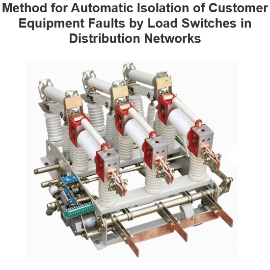
Method for Automatic Isolation of Customer Equipment Faults by Load Switches in Distribution Networks
1 OverviewDistribution network safety has long been under - addressed, with its automation lagging substation automation . Using 10 kV intervals of existing substations to set line section points meets future grid needs . Configuration of distribution switches, section switches, and protection must match substation outgoing - line protection for reliability. Fault isolation, self - healing, and restoration are key to distribution automation .Scholars have studied smart distribution network fault
Felix Spark
06/30/2025
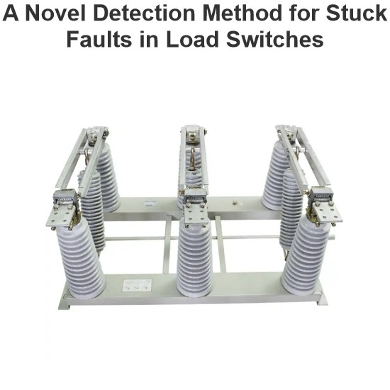
A Novel Detection Method for Stuck Faults in Load Switches
In recent years, as distribution automation advances, load switches see wider use in distribution lines. Yet, mechanical - failure - induced accidents are on the rise, burdening line operation and maintenance.Poor mechanical performance is the main cause of switch faults. Many scholars study large - scale switchgear operation, using methods like coil current detection, vibration signal analysis, switch travel testing, ultrasonic flaw detection, and infrared thermometry. Motor - current - based s
Oliver Watts
06/30/2025
What You Need to Know About Load Switch Malfunctions
Hey there, I’m Blue — been working as an electrical engineer for more than 20 years now.I’ve spent most of my career designing circuit breakers, managing transformers, and helping power companies solve all sorts of electrical system challenges.Today, a friend from Southeast Asia asked me:"What are the common faults of load switches?"Great question! So let’s break it down in simple terms — no fancy jargon, just real-world stuff you might actually see on the job or during maintenance.First, What E
Master Electrician
06/30/2025
What tests need to be conducted for load switches?
As a technician with years of on-site experience in power testing, I understand the importance and complexity of load switch testing. Below, I combine practical work experience to elaborate on the full process of load switch testing, from testing items and methods to equipment and procedural specifications.I. Routine Electrical Performance Testing(1) Loop Resistance TestLoop resistance is a core indicator for evaluating a load switch's conductivity. I strictly follow GB/T 3804 and GB 1984 standa
Oliver Watts
06/28/2025
Inquiry
Download
Experts Electrical is dedicated to serving the personnel in the global power industry.
Join Experts Electrical, not only can you discover power equipment and power knowledge, but also canhnd like - minded friends!