Method for Automatic Isolation of Customer Equipment Faults by Load Switches in Distribution Networks

Felix Spark
06/30/2025
Hey there! I'm an electrical engineer specializing in Failure and Maintenance. I've dedicated my career to ensuring the seamless operation of electrical systems. I excel at diagnosing complex electrical failures, from malfunctioning industrial motors to glitchy power distribution networks. Using state - of - the - art diagnostic tools and my in - depth knowledge, I pinpoint issues quickly. On this platform, I'm eager to share my insights, exchange ideas, and collaborate with fellow experts. Let's work together to enhance the reliability of electrical setups.
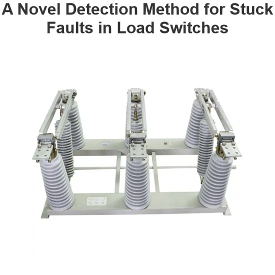
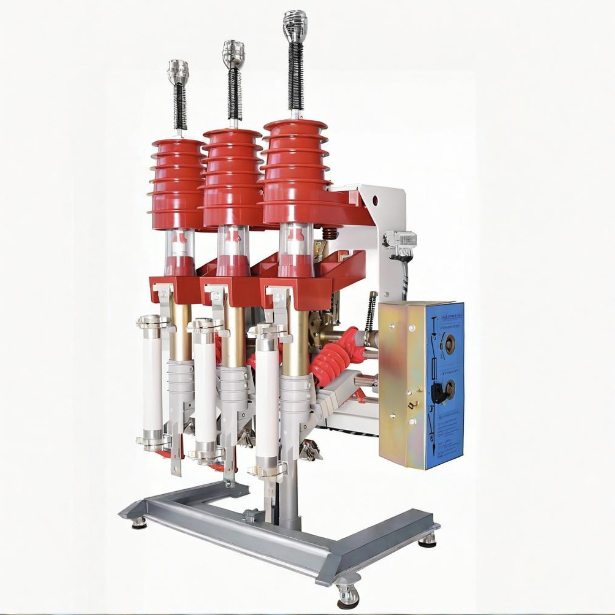
A Novel Detection Method for Stuck Faults in Load Switches
In recent years, as distribution automation advances, load switches see wider use in distribution lines. Yet, mechanical - failure - induced accidents are on the rise, burdening line operation and maintenance.Poor mechanical performance is the main cause of switch faults. Many scholars study large - scale switchgear operation, using methods like coil current detection, vibration signal analysis, switch travel testing, ultrasonic flaw detection, and infrared thermometry. Motor - current - based s
Oliver Watts
06/30/2025
What You Need to Know About Load Switch Malfunctions
Hey there, I’m Blue — been working as an electrical engineer for more than 20 years now.I’ve spent most of my career designing circuit breakers, managing transformers, and helping power companies solve all sorts of electrical system challenges.Today, a friend from Southeast Asia asked me:"What are the common faults of load switches?"Great question! So let’s break it down in simple terms — no fancy jargon, just real-world stuff you might actually see on the job or during maintenance.First, What E
Master Electrician
06/30/2025
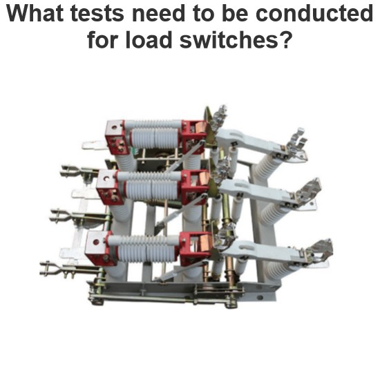
What tests need to be conducted for load switches?
As a technician with years of on-site experience in power testing, I understand the importance and complexity of load switch testing. Below, I combine practical work experience to elaborate on the full process of load switch testing, from testing items and methods to equipment and procedural specifications.I. Routine Electrical Performance Testing(1) Loop Resistance TestLoop resistance is a core indicator for evaluating a load switch's conductivity. I strictly follow GB/T 3804 and GB 1984 standa
Oliver Watts
06/28/2025
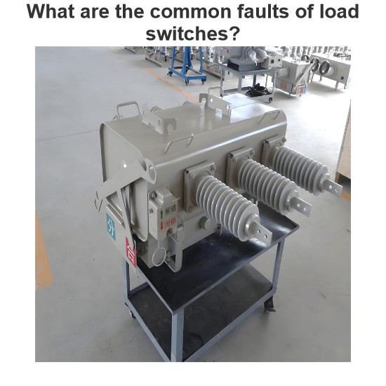
What are the common faults of load switches?
As an on-site maintenance technician, I frequently deal with electrical, mechanical, and insulation faults in load switches. The following outlines fault manifestations, causes, and solutions:I. Electrical Fault Handling(1) Contact HeatingContact heating is mainly caused by poor contact, insufficient pressure, or three-phase asynchrony. When the contact resistance exceeds 1.5 times the initial value, the temperature rise will exceed the standard in a 40℃ environment. For example, the FW4-10 swit
Felix Spark
06/28/2025


