• Complete Set of Large Capacity 100kA Generator Circuit Breaker
Complete Set of Large Capacity 100kA Generator Circuit Breaker
discuss personally
Model
ZHN10-24/15000-120
Basic info
Brand ROCKWILL
Model NO. Complete Set of Large Capacity 100kA Generator Circuit Breaker
Rated voltage 24kV
Rated normal current 15000
Series Circuit Breaker
Product Detail

Description:

This product is suitable for water and thermal power plants with a single generator unit capacity of 300-400 megawatts. It has a large current carrying capacity and strong breaking capacity. It was appraised by the China Machinery Industry Federation in 2019, and its comprehensive technical performance has reached the international leading level. Currently, it has supplied multiple power plants.

Product Performance:

  • Implemented according to the latest lEC standards.

  • High insulation level: meeting the insulation requirements of the products under the environment of 3,000m above sea level.

  • High long-term flow capacity: adopts natural cooling, no auxiliary heat dissipation device, and rated flow capacity up to 15,000A.

  • Excellent breaking performance: The effective values of Ac component of short-circuit breaking current is 100kA and the DC component is as high as 82%, which meets the current breaking requirements under various fault conditions.

  • High mechanical reliability: Innovative design of circuit breaker drive ensures that the product can meet the breaking performance under the small input operation work, and realize the mechanical life requirement of operation for 10,000times.

  • Comprehensive safety protection measures: Pressure release device is installed at the top of the circuit breaker When the gas pressure in the arc extinguishing chamber exceeds 1.2Pa due to an accident, the gas will be released to ensure the safety of the personnel and surrounding equipment, The product design can ensure the stable operation of the power plant.
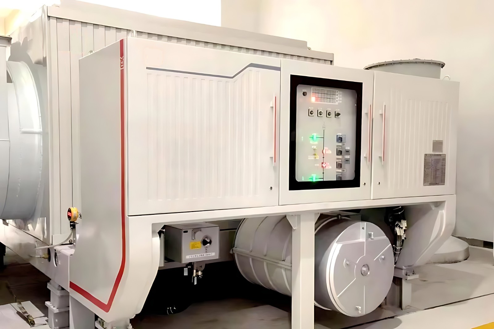
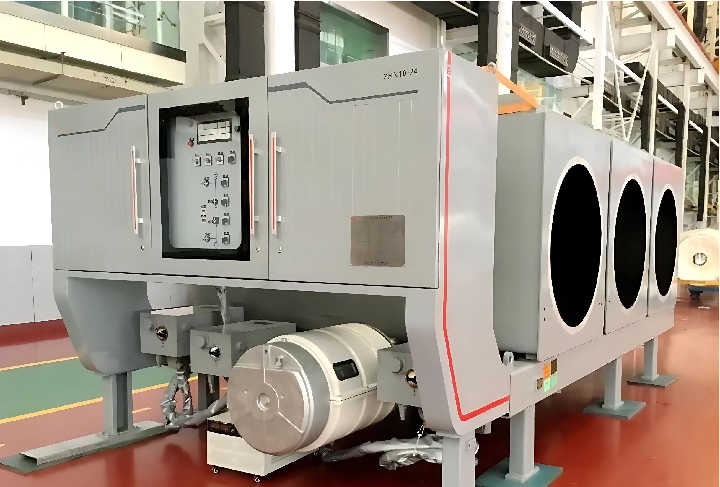
Product Structure:

  • The product consists of three single poles, and each pole has an individual enclosed metal enclosure mounted on the same chassis.

  • Circuit breaker is equipped with hydraulic spring operating mechanism: the disconnector and earthing switch are equipped with motor operating mechanism; the driving modes are all three phase mechanical linkage.

  • The main circuit adopts natural cooling.

  • Each operating mechanism is installed on the side of the product close to the control cabinet.

  • SF6 is used as arc extinguishing and insulation medium for circuit breaker, and the arc extinguishing chamber adopts a new type of arc extinguishing chamber which combines self-energy arc extinguishing with auxiliary air-compressor arc extinguishing, which effectively reduces the operating work and perfectly solves the problem of short-circuit current breaking of various energies.

  • The disconnector and the circuit breaker are connected in series, arranged in the same enclosure, using the air as the insulation medium, the fixed contact is located at the circuit breaker side, and the moving contact is in the telescopic direct-acting structure, which has the advantages of simple structure with small occupancy size and high current capability.

  • The earthing switches are arranged on both sides of the incoming and cut going lines respectively, and using the air as the insulation medium, The fixed contacts are located on the high potential side, which are installed on the support of the main circuit, and the moving side is installed on the bottom plate of the box body. The moving contacts are connected with the single-phase enclosure and form earthing loop through the metal-enclosed isolated phase busbars connected with the moving contacts.
    微信图片_20240615104709_修复后.png

Typical applications:
微信图片_20240615104755_修复后.png

微信图片_20240615104813_修复后.png

Main technical parameters:

image.png

What is a generator circuit breaker?

A generator circuit breaker is a special type of circuit breaker used to connect a generator to the power grid system. Its primary functions are to control the synchronization and disconnection of the generator with the grid under normal conditions, which means it enables the connection and disconnection of the generator to and from the grid. For example, once the generator starts up and reaches its rated parameters, the generator circuit breaker is used to connect it to the grid, allowing the generator to begin supplying electrical power to the grid. Additionally, in the event of a generator fault (such as a short circuit or overload) or a grid-side fault that could affect the safe operation of the generator, the generator circuit breaker can quickly disconnect the electrical connection between the generator and the grid, thereby protecting both the generator and the grid system.

Know your supplier
ROCKWILL
Rockwill Electric Group Global Manufacturer of High voltage and medium-voltage power equipment and smart grid solutions. Headquartered in Wenzhou, China. Serving 100+ countries with quality, innovation, and trust. What We Offer: • HV-MV switchgear (VCB, SF₆ circuit breakers, RMU, GIS) • Distribution transformers and substations • Smart grid and monitoring systems • Solar, wind, EV charging, and energy storage solutions • EPC turnkey power projects Certified: ISO 9001 / ISO 14001 / ISO 45001
Main Categories
High voltage
Business Type
Design/Manufacture/Sales
Highest Annual Export (USD)
$150,000,000
Professional Experience
16 years
Workplace
108000m²m²
占位
占位
Related Products
Related Knowledges
What is Transformer Vector Groups?
Transformer Vector Group DefinitionThe transformer vector group denotes the phase difference between the primary and secondary sides of a transformer, while also defining the arrangement of high-voltage and low-voltage windings in three-phase transformers. Vector groups are determined by the connection configurations of three-phase transformers, which can be categorized into four main groups based on the phase difference between corresponding line voltages of the high-voltage and low-voltage sid
Edwiin
06/02/2025
What is a Pure Resistive AC Circuit?
Pure Resistive AC CircuitA circuit containing only a pure resistanceR(in ohms) in an AC system is defined as a Pure Resistive AC Circuit, devoid of inductance and capacitance. Alternating current and voltage in such a circuit oscillate bidirectionally, generating a sine wave (sinusoidal waveform). In this configuration, power is dissipated by the resistor, with voltage and current in perfect phase—both reaching their peak values simultaneously. As a passive component, the resistor neither
Edwiin
06/02/2025
What is a Pure Capacitor Circuit?
Pure Capacitor CircuitA circuit comprising only a pure capacitor with capacitanceC(measured in farads) is termed a Pure Capacitor Circuit. Capacitors store electrical energy within an electric field, a characteristic known ascapacitance(alternatively referred to as a "condenser"). Structurally, a capacitor consists of two conductive plates separated by a dielectric medium—common dielectric materials include glass, paper, mica, and oxide layers. In an ideal AC capacitor circuit, the current
Edwiin
06/02/2025
Resonant Frequency
Resonant Frequency
In a series circuit, the resonant frequency condition occurs when the inductive reactance equals the capacitive reactance. Changing the supply frequency alters the values of XL = 2πfL and XC = 1/2πfC.As the frequency increases, XL rises whileXC falls. Conversely, a decrease in frequency causesXL to drop andXCto rise.To achieve series resonance, the frequency is tuned to fr(pointP in the curve below), whereXL = XC.At series resonance, when XL = XCWhere frdenotes the resonant frequency in he
Edwiin
06/02/2025
Current Division and Voltage Division Rule
Current Division RuleA parallel circuit functions as a current divider, where the incoming current splits among all branches while the voltage across each branch remains constant. The Current Division Rule is used to determine the current through circuit impedances, as illustrated by the circuit below:The currentI splits intoI1 andI2 across two parallel branches with resistancesR1 andR2, whereVdenotes the voltage drop across both resistances. As is known,Then the equation of the current is writt
Edwiin
06/02/2025
Mesh Current Analysis Method
The Mesh Current Analysis Method is utilized to analyze and solve electrical networks with multiple sources or circuits comprising numerous meshes (loops) containing voltage or current sources. Also known as the Loop Current Method, this approach involves assuming a distinct current for each loop and determining the polarities of voltage drops across loop elements based on the assumed direction of the loop current.In mesh current analysis, the unknowns are the currents in different meshes, and t
Edwiin
06/02/2025
×
Inquiry
Download
Experts Electrical is dedicated to serving the personnel in the global power industry.
Join Experts Electrical, not only can you discover power equipment and power knowledge, but also canhnd like - minded friends!
商品视频播放