Search
English
English
Español
Français
العربية
Русский
Português
हिन्दी
বাংলা
Deutsch
日本語
Bahasa Indonesia
Italiano
RFQ
Home
Market
Solutions
Knowledge
Download the app
MENU
Home
Market
Solutions
Knowledge
English
English
Español
Français
العربية
Русский
Português
हिन्दी
বাংলা
Deutsch
日本語
Bahasa Indonesia
Italiano
Home
Knowledge
Topics
Power Systems
Power system
Machines
circuit diagram
Measurement
Basic Electrical
Basic
Industrial circuit
Basic knowledge
Electric Power Knowledge
Transmission
Control
Motor
Transformer
Electric Motors
Protection
household circuit
Generation
Control Circuit
Circuit Theory
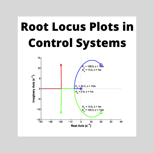
Root Locus Technique in Control System | Root Locus Plot
The root locus technique in control system was first introduced in the year 1948 by Evans. Any physical system is represented by a transfer function in the form ofWe can find poles and zeros from G(s). The location of poles and zeros are crucial keeping view stability, relative stability, transient response and error analysis. When the system is put to service stray inductance and capacitance get into the system, thus changes the location of poles and zeros. In root locus technique in control sy
Electrical4u
03/29/2024
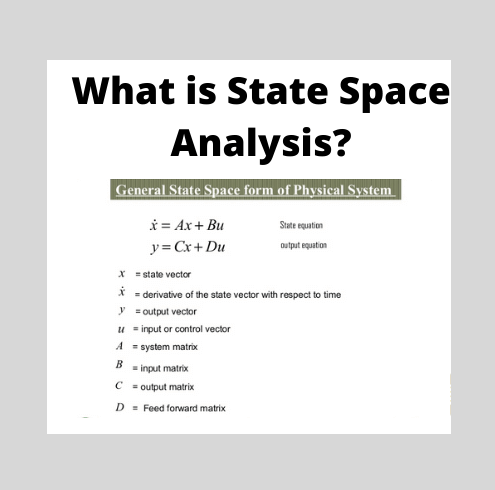
State Space Analysis of Control System
Before I introduce you about the concept of state space analysis of control system, it is very important to discuss here the differences between the conventional theory of control system and modern theory of control system. The conventional control theory is completely based on the frequency domain approach while the modern control system theory is based on time domain approach. In the conventional theory of control system we have linear and time invariant single input single output (SISO) syste
Electrical4u
03/29/2024
Transient and Steady State Response in a Control System
When we study the analysis of the transient state and steady state response of control system it is very essential to know a few basic terms and these are described below.Standard Input Signals : These are also known as test input signals. The input signal is very complex in nature, it is complex because it may be a combination of various other signals. Thus it is very difficult to analyze characteristic performance of any system by applying these signals. So we use test signals or standard inpu
Electrical4u
03/29/2024
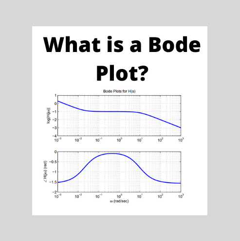
Bode Plot, Gain Margin and Phase Margin (Plus Diagrams)
What is a Bode Plot?A Bode plot is a graph commonly used in control system engineering to determine the stability of a control system. A Bode plot maps the frequency response of the system through two graphs – the Bode magnitude plot (expressing the magnitude in decibels) and the Bode phase plot (expressing the phase shift in degrees).Bode plots were first introduced in the 1930s by Hendrik Wade Bode while he was working at Bell Labs in the United States. Although Bode plots offer a relatively s
Electrical4u
03/29/2024
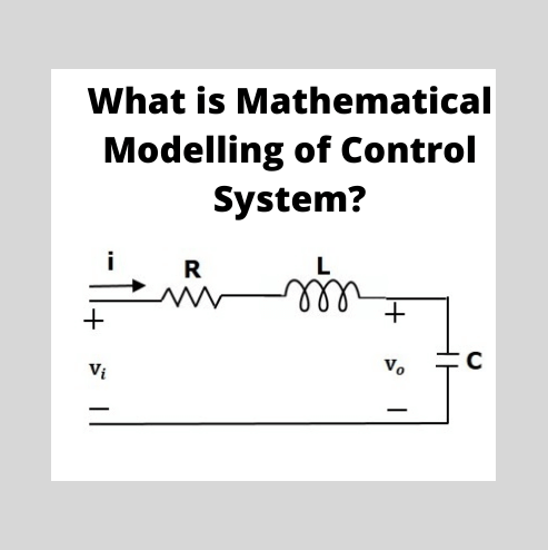
Mathematical Modelling of Control System | Mechanical Electrical
Mathematical Modelling of Control SystemThere are various types of physical systems, namely we have: Mechanical systems Electrical systems Electronic systems Thermal systems Hydraulic systems Chemical systemsFirst off we need to understand – why do we need to model these systems in the first place? Mathematical modeling of a control system is the process of drawing the block diagrams for these types of systems in order to determine their performance and transfer functions.Now let us describe the
Electrical4u
03/29/2024
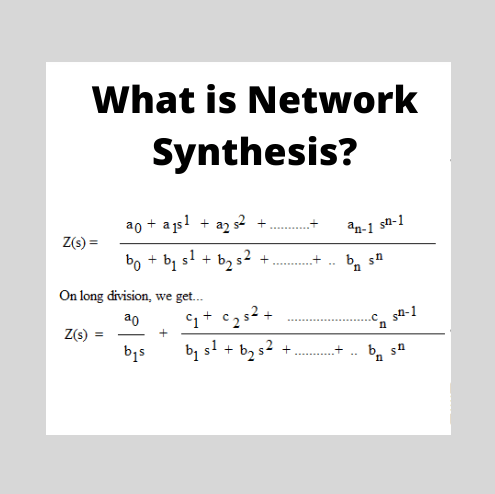
Network Synthesis | Hurwitz Polynomial | Positive Real Functions
Theory of Network SynthesisNetwork FunctionsNetwork synthesis theory involves the synthesis of networks made up of both active components (like resistors) and passive components (like inductors and capacitors).Let’s start with the basics: what is a network function? In the frequency domain, network functions are defined as the quotient obtained by dividing the phasor corresponding to the circuit output by the phasor corresponding to the circuit input.In simple words, network functions are the ra
Electrical4u
03/29/2024
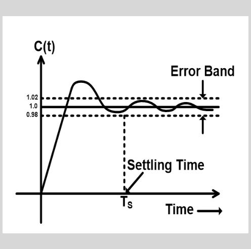
Settling Time: What is it? (Formula And How To Find it in MATLAB)
What is Settling Time?The settling time of a dynamic system is defined as the time required for the output to reach and steady within a given tolerance band. It is denoted as Ts. Settling time comprises propagation delay and time required to reach the region of its final value. It includes the time to recover the overload condition incorporated with slew and steady near to the tolerance band.The tolerance band is a maximum allowable range in which the output can be settle. Generally, the toleran
Electrical4u
03/29/2024
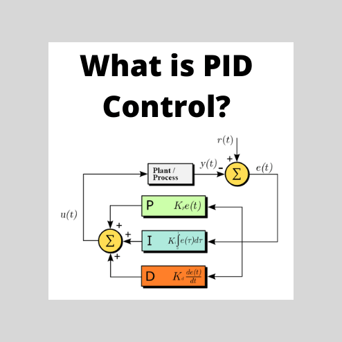
PID Controllers and PID Control in Control Systems
PID control stands for proportional–integral–derivative control. PID control is a feedback mechanism used in a control system. This type of control is also termed as three-term control, and is implemented by a PID Controller. By calculating and controlling three parameters – the proportional, integral and derivative of how much a process variable deviates from the desired set point value – we can achieve different control actions for specific work.PID controllers are considered to be the best co
Electrical4u
03/29/2024
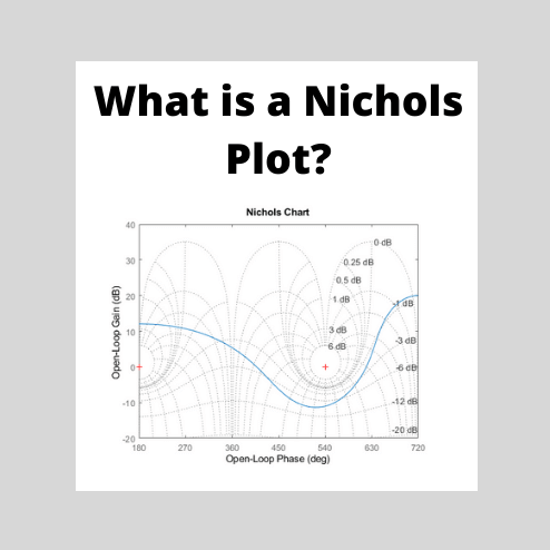
Nichols Chart: What is it?
What is a Nichols Chart?A Nichols Chart (also known as a Nichols Plot) is a plot used in signal processing and control system design to determine the stability and closed-loop frequency response of a feedback system. The Nichols chart is named after its founder, Nathaniel B. Nichols.How Does A Nichols Chart Work?Constant magnitude loci that are M-circles and constant phase angle loci that are N-circles are the fundamental components in designing the Nichols chart.The constant M and constant N ci
Electrical4u
03/29/2024
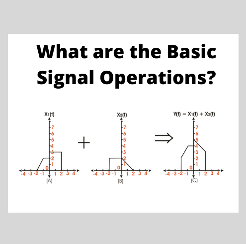
Basic Signal Operations
A signal, comprises of a set of information expressed as a function of any number of independent variables, that can be given as an input to a system, or derived as output from the system, to realize its true practical utility. The signal we derive out of a complex system might not always be in the form we want,∴ being well acquainted with some basic signal operations may come really handy to enhance the understandability and applicability of signals.The mathematical transformation from one sign
Electrical4u
03/29/2024
1
2
···
229
230
231
232
233
···
299
300
Source professional electrical partners, experts, and explore smart grid & energy solutions.
Inquiry
Send Now
Download
Experts Electrical is dedicated to serving the personnel in the global power industry.
Join Experts Electrical, not only can you discover power equipment and power knowledge, but also canhnd like - minded friends!