| Brand | Wone |
| Model NO. | PG208 Protected Pressure Transmitter |
| Power supply | 9~30VDC |
| Type of pressure | Gauge pressure |
| display | Yes |
| Series | PG208 |
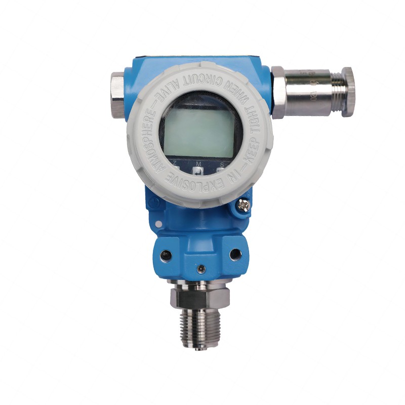
Description
The protective pressure transmitter adopts imported silicon wafers, with high precision and stable performance; As a sensing element, the silicon piezoresistive pressure core has a built-in processing circuit that converts the millivolt signal of the sensor into a standard voltage and current signal, and combines it with the unit instrument, DCS system, PLC, etc. to form an automatic control system, which is an ideal pressure measuring instrument in the field of industrial automation. It is an ideal pressure measuring instrument in the field of industrial automation to form an automatic control system.
Industry applications
It is widely used in various industrial fields (automation equipment and petroleum, chemical, natural gas, energy, etc.) where fluid pressure needs to be measured.
Features
Diaphragm isolation technology is adopted, which has high stability and high reliability.
Integrated chip, wide voltage power supply.
Integral die-cast aluminum structure, strong and reliable.
Frequency cut-off design, strong anti-interference ability, lightning protection.
Current limiting, voltage limiting, reverse polarity protection (current limiting output).
High precision, good stability, fast response speed and impact resistance.
Technical parameters
| Measuring medium | Liquids or gases (compatible with contact materials) |
| Pressure range | - 100 k Pa~ 0 ~ 100 MPa |
| Pressure mode | Gauge pressure, absolute pressure, negative pressure |
| Output signal | 4 ~ 20 m A 0 ~ 10 VDC 0 ~ 5 VDC RS 485 customized |
| Supply voltage | 9 ~ 30 VDC |
| Accuracy class | ± 0.25 % FS ± 0.5 % FS Header display accuracy 0 . 5-level, digital tube (LED) display |
| working conditions | Medium temperature - 40 ~ 80 °C Ambient temperature - 40 ~ 80 °C |
| Seismic performance | 10 g( 20 ... 2000 Hz) |
| Overload capacity | 1.5 times ~ 5 times |
| Frequency of response | Analog signal output ≤ 500 Hz and digital signal output ≤ 5 Hz |
| Stable performance | ± 0 . 1 % FS/year |
| Temperature drift | ±0 . 01 % FS/ °C (within temperature compensation) |
| Ingress protection | IP 65 IP 66 |
| Explosion-proof type | Flameproof ExdII.CT 6 Gb Intrinsically Safe ExiaII.CT 6 Ga |
| Load characteristics | Current load ≤{(Us- 7.5 )÷ 0.02 ( Us=supply voltage)}Ω Voltage load≥ 100 k Ω |
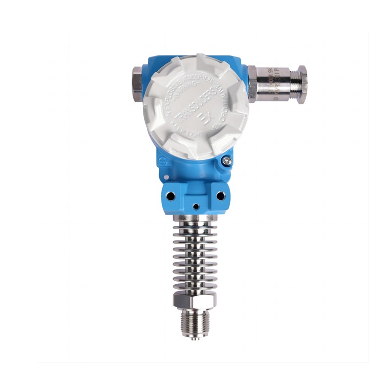
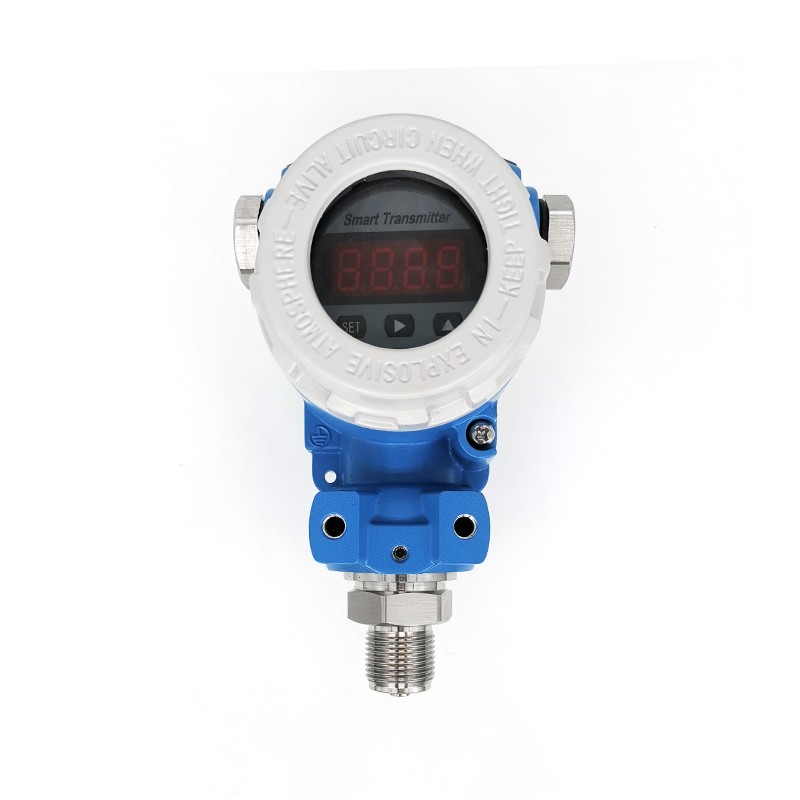
Product show