• 40.5kV 72.5kV 126kV 252kV 363kV 500kV 800kV HV Grounding Switch
40.5kV 72.5kV 126kV 252kV 363kV 500kV 800kV HV Grounding Switch
discuss personally
Model
JW8-800-63
JW8-550-63
JW8-363-63
JW6-252-50
JW6-126-40
JW6-72.5-40
JW6-40.5-40
Basic info
Brand ROCKWILL
Model NO. JW6(8) Series HV Grounding Switch
Rated voltage 800kV
Series JW6(8) Series
Product Detail

Description

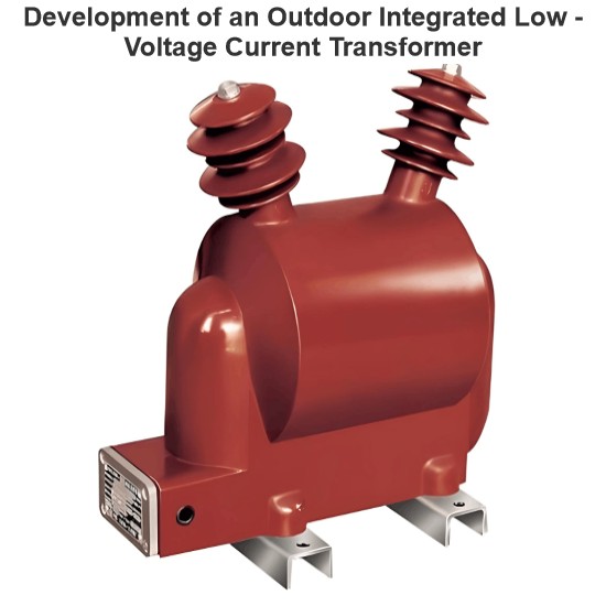
The JW6/8 series high-voltage grounding switches feature a three-single-pole configuration integrated with an operating mechanism. Each single pole comprises a base, a pillar insulator, and a conductive rod: the rod is mounted on the base, while the static contact is positioned at the top of the insulator.

Driven by the operating mechanism, the conductive rod rotates upward from the horizontal position via transmission components, latching or inserting into the static contact to achieve switch closure; the opening process reverses this motion.

Main Features:


  • Streamlined Design & Versatility:The product’s simple, rational structure enables effortless assembly, transportation, installation, and debugging, adapting to diverse field requirements.

  • High-Performance Conductive Components:Constructed from high-strength alloy profiles, the conductive rods offer excellent electrical conductivity, robust mechanical strength, and lightweight design. Their superior anti-corrosion properties ensure prolonged service life in harsh environments.

Technical parameter:

1732242955389.png

How is the indoor high-voltage AC grounding switch electrically tested?

  • Insulation Resistance Test: Use an insulation resistance tester to measure the insulation resistance of the grounding switch. The insulation resistance value should meet the product standards and relevant electrical codes. Generally, for indoor high-voltage AC grounding switches, the insulation resistance should be in the range of several gigohms or more to ensure good insulation performance during operation and prevent leakage accidents.

  • Loop Resistance Test: Measure the loop resistance of the grounding switch using a dedicated loop resistance tester to check if the contact points are in good condition. The loop resistance value should fall within the specified range. If the loop resistance is too high, it may cause significant heating when current flows through the grounding switch, affecting its normal operation.

  • Grounding Performance Check: Ensure that the grounding connection is reliable and that the grounding resistance meets the requirements. If the grounding resistance is too high, it may prevent the current from being effectively discharged to the ground during a fault, thus failing to provide adequate protection for maintenance personnel and equipment.

Know your supplier
ROCKWILL
Rockwill Electric Group Global Manufacturer of High voltage and medium-voltage power equipment and smart grid solutions. Headquartered in Wenzhou, China. Serving 100+ countries with quality, innovation, and trust. What We Offer: • HV-MV switchgear (VCB, SF₆ circuit breakers, RMU, GIS) • Distribution transformers and substations • Smart grid and monitoring systems • Solar, wind, EV charging, and energy storage solutions • EPC turnkey power projects Certified: ISO 9001 / ISO 14001 / ISO 45001
Main Categories
High voltage
Business Type
Design/Manufacture/Sales
Highest Annual Export (USD)
$150,000,000
Professional Experience
16 years
Workplace
108000m²m²
占位
占位
Related Knowledges
Failure Analysis and Design Optimization of Conventional Grounding Transformers
I. Core Cause of Damage: Electrodynamic Impact (Complying with GB/T 1094.5 / IEC 60076-5)The direct cause of high-voltage winding end collapse is the instantaneous electrodynamic impact induced by short-circuit current. When a single-phase grounding fault occurs in the system (such as lightning overvoltage, insulation breakdown, etc.), the grounding transformer, as the fault current path, withstands high-amplitude and steep-rise-rate short-circuit currents. According to Ampère's force law
Felix Spark
06/12/2025
Analysis of Grounding Transformer Operational Behavior Under System Single-Phase-to-Ground Fault Conditions
1 Theoretical AnalysisIn distribution networks, grounding transformers serve two key roles: powering low - voltage loads and connecting arc - suppression coils at neutrals for grounding protection. Grounding faults, the most common distribution network fault, heavily impact transformers’ operating characteristics, causing sharp changes in electromagnetic parameters and status.To study transformers’ dynamic behaviors under single - phase grounding faults, build this model: Assume a tr
Felix Spark
06/12/2025
Design Calculations for Neutral Grounding Schemes and Grounding Transformer Sizing in Utility-Scale Solar PV Plants
1 Classification of Neutral Grounding Methods for Solar Photovoltaic Power StationsInfluenced by differences in voltage levels and grid structures across regions, the neutral grounding methods of power systems are mainly categorized into non-effective grounding and effective grounding. Non-effective grounding includes neutral grounding via arc suppression coils and neutral ungrounded systems, while effective grounding comprises neutral solid grounding and neutral grounding via resistors. The sel
Dyson
06/12/2025
Zero-Sequence Impedance Characterization of Dry-Type Grounding Transformer with ZN Connection
In a neutral-insulated three-phase power system, an earthing transformer provides an artificial neutral point, which can be solidly earthed or earthed via reactors/arc suppression coils. The ZNyn11 connection is typical, where zero-sequence magnetomotive forces in the inner/outer half-windings of the same core column cancel out, balancing fault currents in series windings and minimizing zero-sequence leakage flux/impedance.Zero-sequence impedance is critical: it determines fault current magnitud
Dyson
06/12/2025
Case Analysis on Maloperation of Grounding Transformer Overcurrent Protection Relay
The neutral grounding mode refers to the connection between the power system neutral point and ground. In China's 35 kV and below systems, common methods include ungrounded neutral, arc-suppression coil grounding, and small-resistance grounding. The ungrounded mode is widely used as it allows short-term operation during single-phase grounding faults, while small-resistance grounding has become mainstream for its fast fault removal and overvoltage limitation. Many substations install grounding tr
Felix Spark
06/12/2025
Discussion on the Design of Low Zero-Sequence Impedance Grounding Transformers
With the expansion of power system scale and the cableization process of urban power grids, the capacitive current in 6kV/10kV/35kV power grids has significantly increased (generally exceeding 10A). As power grids at this voltage level mostly adopt neutral ungrounded operation mode, and the distribution voltage side of main transformers is usually in delta connection, lacking a natural grounding point, the arc during ground faults cannot be reliably extinguished, necessitating the introduction o
Dyson
06/11/2025
×
Inquiry
Download
Experts Electrical is dedicated to serving the personnel in the global power industry.
Join Experts Electrical, not only can you discover power equipment and power knowledge, but also canhnd like - minded friends!
商品视频播放