Ratio Trial Verification Method for Current Transformers
Oliver Watts
07/05/2025

Topics
Hey! I'm Oliver Watts, an electrical engineer in Inspection and Testing. With years of hands - on experience, I ensure electrical systems meet top safety and performance standards. Using advanced gear, I conduct diverse tests, easily spotting issues in both large - scale industrial and small - scale commercial setups. I love teaming up, sharing knowledge, and keeping up with industry regs. Also, I'm skilled at data analysis with software. If you're into electrical inspection or just want to chat engineering, reach out. Let's connect and explore!
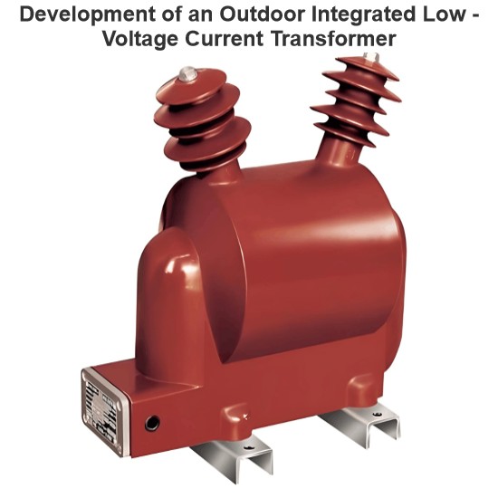
Development of an Outdoor Integrated Low - Voltage Current Transformer
In power grid construction, line losses reflect planning, design, and operation management. They’re key for evaluating power systems. For refined low - voltage transformer area line loss management, accurate line loss counting is critical. So, solidifying basic data, ensuring data accuracy, and proper original data collection matter for analysis. We must also optimize factors affecting collection accuracy, make preventive measures, and boost refined line loss management.1 Current Status of
Dyson
07/05/2025
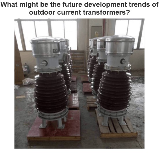
What might be the future development trends of outdoor current transformers?
I'm Echo, a 12-Year Veteran in the CT Industry, Talking About What's Coming NextHi everyone, I'm Echo, and I've been working in the current transformer (CT) industry for 12 years.From learning wiring and equipment debugging with my mentor to now leading a team tackling complex on-site issues, I've witnessed many technological advancements and industry changes. Especially with outdoor current transformers, there have been significant developments, but also much room for improvement.A few days ago
Echo
07/05/2025
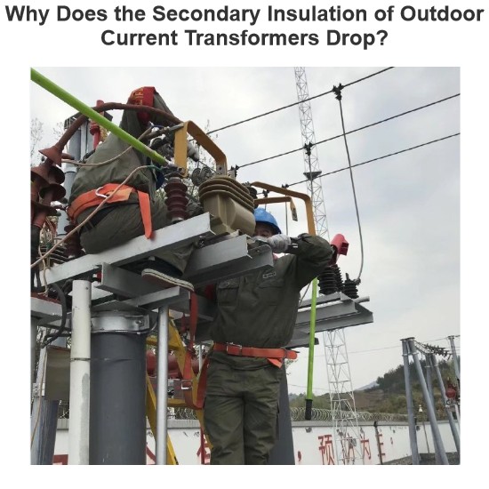
Why Does the Secondary Insulation of Outdoor Current Transformers Drop?
I'm Felix, a 15-Year Veteran in the CT Industry, Sharing What You Need to Watch Out ForHi everyone, I'm Felix, and I've been working with current transformers (CTs) for over 15 years. Today, let’s talk about why the secondary insulation of outdoor CTs sometimes drops, and what you can do to prevent it.Common Causes:1. Moisture Ingress — Poor Sealing is the Biggest Problem!Outdoor CTs are constantly exposed to wind and rain. If the sealing isn't tight enough, moisture can get inside a
Felix Spark
07/05/2025
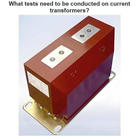
What tests need to be conducted on current transformers?
By Oliver, 8 Years in the Electrical IndustryHi everyone, I'm Oliver, and I've been working in the electrical industry for 8 years.From early days doing substation equipment commissioning to now managing protection and metering configurations for entire distribution systems, one of the most frequently used devices in my work has been the Current Transformer (CT).Recently, a friend who's just starting out asked me:“How do you test current transformers? Is there a simple and effective way to
Oliver Watts
07/04/2025


