Development of an Outdoor Integrated Low - Voltage Current Transformer

Dyson
07/05/2025

In power grid construction, line losses reflect planning, design, and operation management. They’re key for evaluating power systems. For refined low - voltage transformer area line loss management, accurate line loss counting is critical. So, solidifying basic data, ensuring data accuracy, and proper original data collection matter for analysis. We must also optimize factors affecting collection accuracy, make preventive measures, and boost refined line loss management.
1 Current Status of Refined Line Loss Collection in Low - voltage Transformer Areas
Since 2013, a municipal power company has advanced full - coverage refined line loss work. After over 6 years, current transformers for electricity collection, damaged by nature, see protective shields detach. Exposed to the environment, they crack under sunlight, risking further damage.
Some transformers for refined line loss collection in low - voltage areas are installed on suspended cables. High winds make them swing, and background data shows total meter data is wind - affected. Thus, improving and updating these transformers is needed to remove hazards and enhance management.
Currently, silicone rubber shields are used on local low - voltage transformer area current transformers for UV and rain protection. But different shield fixing methods cause some to detach over time. Also, transformers under fuse boxes on separate supports, though wind - resistant, let water in from the bottom, rusting cores and affecting accuracy.
2 Ideas for Developing Electricity Collection Devices
R & D uses mature, reliable equipment and components, leveraging proven solutions. Key research:
2.1 Special - purpose Current Transformer Design
Design a transformer for outdoor use, live - line installation (open structure), and cable - holding. Its split parts fix to the line pole cross - arm, meeting the local power company’s electrical parameter requirements for distribution transformer electricity collection box upgrades.
2.2 Puncture Power - taking Device Research
Develop a device to take power from the transformer’s bus cable for metering and control. It integrates with the transformer. Insulation between the cable puncture point and the transformer’s secondary winding must be 1.2 times that of general 3 kV (1 - minute power - frequency withstand voltage) low - voltage transformers. Insulation between the puncture point and the transformer’s support must also meet this standard.
The voltage from the puncture needle passes through a switch (integrated with the transformer) before being led out.
2.3 Environmental Adaptability Design
The device must be waterproof, moisture - proof, UV - resistant, work long - term at - 25℃ to 70℃, withstand level 12 typhoons and level 8 earthquakes, and have IP67 protection.
Sample Test Items
Samples undergo tests including:
  • Current transformer tests: accuracy, instrument security coefficient, withstand voltage, rain, and mechanical strength tests.
  • Puncture unit tests: conduction, impact, insulation resistance, DC resistance, temperature rise, and cable tension tests.
  • Overall device tests: mechanical impact, insulating shell heat resistance, and protection level tests.
3 Development of Outdoor Integrated Low - voltage Devices
3.1 Outdoor Integrated Low - voltage Current Transformer Design
As the core of the collection device, the transformer abandons the traditional circular design. Using a square body (fitting cement pole cross - arms), it fixes via screws, reducing wind - and vibration - induced accuracy impacts. Secondary leads use 2.5 mm² RV wires; the open structure allows live - line installation.
The core uses Nippon Steel ZW80 0.23 mm silicon steel sheets (separable, high initial permeability, low loss), meeting class 0.5S accuracy. The body is polycarbonate; the interior is epoxy - cast for stability and insulation.
3.2 Puncture Power - taking Unit Design
The puncture needle and switch are at the transformer’s bottom. The needle, perpendicular to the inner hole (pointing to its center), is telescopic (stroke ≥ 1/2 inner hole diameter, adjusted by screws, torque ≥ 1 N·m). Connected to the transformer’s switch, it leads out via 1.5 mm² RV wire. The switch is cast inside, with a silicone - sealed handle for a tight fit.
3.3 Waterproof, Moisture - proof, and UV - proof Design
The transformer body is epoxy - cast for full insulation and sealing. Grooves with silicone seals on split end faces prevent water/moisture ingress.
The switch is cast inside; the movable handle and lead roots are silicone - sealed/integrally cast, with no exposed live points.
Using polycarbonate and silicone rubber (proven UV - resistant, slow - aging, 30 + year service life).
4 Conclusion
The outdoor integrated low - voltage current transformer has a split open structure, enabling easy installation and live - line work. Its split parts fix to the cross - arm, holding cables tightly with strong tensile/shear resistance.
It integrates current/voltage signals (including power) for pole - mounted transformer area collection. A switch on the voltage lead - out meets personalized needs.
The telescopic puncture needle suits cables of varying thicknesses/insulation. With full insulation/sealing (IP67), it ensures reliability.
Currently split - phase (large volume), future optimization into a three - phase structure will adapt to more scenarios, improving power system refined line loss management.
Dyson

Focused on the design of electrical equipment, proficient in electrical principles and relevant specifications, and skilled in using design software. From intelligent substations to various types of electrical equipment, I am adept at optimizing design solutions, integrating new technologies. With practical experience and collaborative management capabilities, I deliver outstanding electrical design achievements.

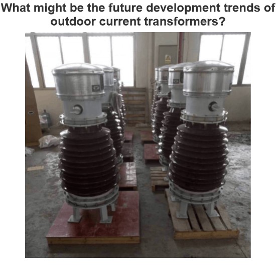
What might be the future development trends of outdoor current transformers?
I'm Echo, a 12-Year Veteran in the CT Industry, Talking About What's Coming NextHi everyone, I'm Echo, and I've been working in the current transformer (CT) industry for 12 years.From learning wiring and equipment debugging with my mentor to now leading a team tackling complex on-site issues, I've witnessed many technological advancements and industry changes. Especially with outdoor current transformers, there have been significant developments, but also much room for improvement.A few days ago
Echo
07/05/2025
Ratio Trial Verification Method for Current Transformers
Fellow electric power calibration workers, you must have encountered this situation: The nameplate of an outdoor current transformer has been tormented by wind, sun, rain, and freezing, to the point where the transformation ratio is indistinguishable! Don't panic, we have a solution - use a current transformer calibrator and through the “transformation ratio trial calibration method”, we can figure out the actual transformation ratio and errors clearly. Here, taking the SHGQ - DC typ
Oliver Watts
07/05/2025
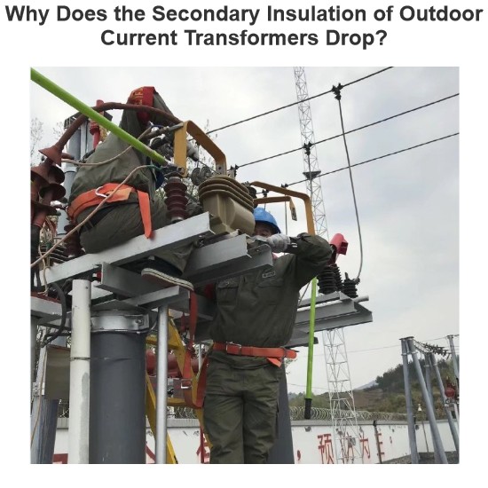
Why Does the Secondary Insulation of Outdoor Current Transformers Drop?
I'm Felix, a 15-Year Veteran in the CT Industry, Sharing What You Need to Watch Out ForHi everyone, I'm Felix, and I've been working with current transformers (CTs) for over 15 years. Today, let’s talk about why the secondary insulation of outdoor CTs sometimes drops, and what you can do to prevent it.Common Causes:1. Moisture Ingress — Poor Sealing is the Biggest Problem!Outdoor CTs are constantly exposed to wind and rain. If the sealing isn't tight enough, moisture can get inside a
Felix Spark
07/05/2025
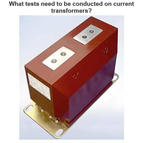
What tests need to be conducted on current transformers?
By Oliver, 8 Years in the Electrical IndustryHi everyone, I'm Oliver, and I've been working in the electrical industry for 8 years.From early days doing substation equipment commissioning to now managing protection and metering configurations for entire distribution systems, one of the most frequently used devices in my work has been the Current Transformer (CT).Recently, a friend who's just starting out asked me:“How do you test current transformers? Is there a simple and effective way to
Oliver Watts
07/04/2025
Inquiry
Download
Experts Electrical is dedicated to serving the personnel in the global power industry.
Join Experts Electrical, not only can you discover power equipment and power knowledge, but also canhnd like - minded friends!