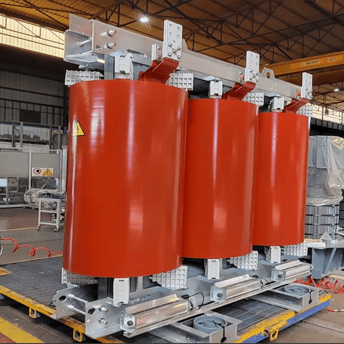
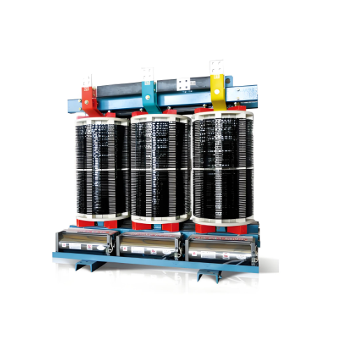
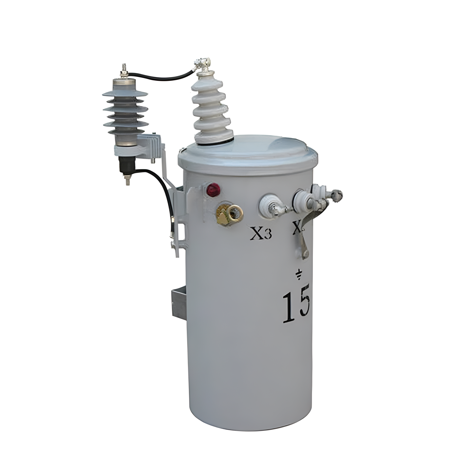
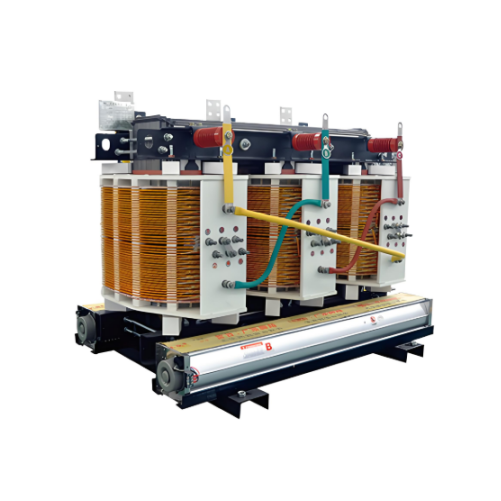
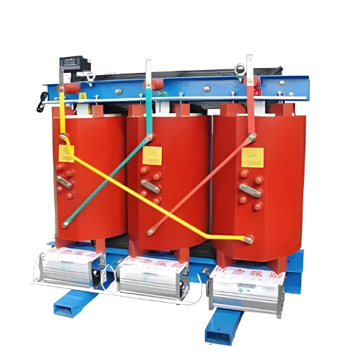
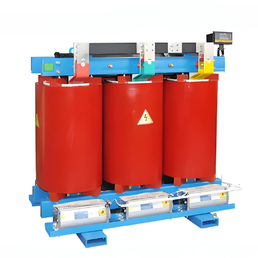
10.5kV Silicon Steel Dry Type Distribution Transformer 630kVA/800kVA/1000kVA/1250kVA /1600kVA/2000kVA
discuss personally
Model
| Brand | Vziman |
| Model NO. | 10.5KV Silicon Steel Dry Type Distribution Transformer 630KVA/800KVA/1000KVA/1250KVA /1600KVA/2000KVA |
| Rated capacity | 2000kVA |
| Voltage grade | 10.5KV |
| Series | SCB |
Feature:
The magnetic core has a miter step joint to ensure optimum performance and minimum sound levels by using step lap technology.
Windings are cast under vacuum with epoxy resin. Transient analysis tests have been performed to verify the electrical stress distribution.
Air-cooling system adopts top-blowing cross flow fan, which has the characteristics of low noise, high wind pressure, beautiful look, etc.
Intelligent temperature controller improves the safety and reliability of the transformer.
Supply various Enclosure options in IP20, IP23, etc.
Parameter:

Installation Location:
Installed in places without fire, explosion hazard, serious pollution, chemical corrosion and cluster vibration, indoor or outdoor.
Supply Ability 500 Set/Sets per Month.
Customized Service:
E2 Environmental Class
C2 Climate Class
F1 Fire Resistance Class
Product Advantages:
Vacuum-Casting
Our product is manufactured with vacuum casting process using a metal pattern, producing a thick resin layer with a smooth surface.
Partial Discharge Free
Lower partial discharge characteristics.
All units are subjected to partial discharge test.
Voltage that is twice that of the operating system is applied to ensure safety.
Partial discharge is less than 10 pC.
Shop Test Items
Routine test:
Routine test is a must test for all transformers in our workshop.
Type test (as requested).
Lightning impulse test.
Temperature-rise test.
Measurement of sound level.
How does the current in the primary winding create an alternating magnetic field in the core?
Relationship between Current and Magnetic Field:
When a current passes through a conductor, a magnetic field will be generated around the conductor. For a transformer, the current in the primary winding will generate a magnetic field in the iron core. The specific steps are as follows:
The current passes through the primary winding:
AC power supply: The primary windings of the transformer are connected to the AC power source, and the current provided by the AC power source is alternating, i.e., the direction and magnitude of the current periodically change with time.
Current waveform: Assuming that the current waveform of the AC power supply is a sine wave, it can be expressed mathematically as I(t)=I0sin(ωt) ,whereI0 is the maximum value of the current,ω is the angular frequency,t is time.
Generation of magnetic field: When the alternating current passes through the primary winding, a magnetic field will be generated around the winding. According to Ampère's circuital law, the magnetic field strength
B generated by the current in a closed loop is proportional to the current.
Direction of magnetic field: The direction of the magnetic field can be determined by the right - hand rule. Point the thumb of the right hand in the direction of the current, and the direction in which the four fingers curl is the direction of the magnetic field.