What are the causes of current transformer faults and the countermeasures for faults?

Felix Spark
07/03/2025

As a front - line maintenance technician, I deal with current transformers (CTs) daily. CTs convert high - magnitude primary current to low - magnitude secondary current for substation/line protection and measurement, operating in series long - term. However, they face faults from external (unbalanced loads, wrong wiring, etc.) and internal (insulation defects) issues. These faults, like secondary open - circuits or insulation breakdown, harm measurement accuracy, protection operation, and grid stability. Below, I share insights from hands - on experience.
1. CT Structure (Maintenance View)
A CT has primary/secondary windings, a core, and insulation (oil - immersed, SF6, solid). The primary winds in series with the circuit, the secondary connects to instruments/relays. Key: Fewer primary turns, more secondary turns, and near - short - circuit normal operation. Critical: Never open the secondary circuit; ground it reliably (I’ve seen dangerous arc flashes from open circuits).
2. Function & Principle (Practical)
CTs reduce large currents for safe protection/measurement via electromagnetic induction, isolating high voltage. During calibrations, I check primary - secondary current ratios to verify CTs.
3. Performance Classification
(1) Optical CTs (OTA)
Based on Faraday magneto - optical effect, used in grid tests. Temperature - sensitive but good for strong magnetic fields.
(2) Low - Power CTs
With microcrystalline alloy cores, they offer wide linear ranges, low losses, and high precision for large currents—ideal for industrial measurements.
(3) Air - Core CTs
No iron core, avoiding magnetic saturation. Popular in relay protection for strong anti - interference, suitable for complex environments.
4. Fault Causes (Field Experience)
(1) Insulation Thermal Breakdown
High - voltage CTs generate heat/dielectric losses. Defective insulation (e.g., uneven wrapping) causes overheating and breakdown—common in old equipment.
(2) Partial Discharge
Normal CT capacitance distributes evenly, but poor manufacturing/structure (e.g., misaligned screens) causes local high fields. Unresolved discharges lead to capacitor failures.
(3) Excessive Secondary Load
Heavy loads in 220 kV systems increase secondary voltage/current, causing errors. Faults may saturate cores, misoperate relays. Open secondary circuits (e.g., loose wires) create high voltages—risky!
5. Fault Response
(1) Follow Operational Rules
  • Wiring: Strictly series - connect circuits, windings, and instruments; use proper configurations (single - phase, star).
  • Error Compensation: Add windings/cores to correct errors via capacitance/inductance.
  • Calibration: Perform demagnetization/polarity tests post - installation/maintenance.

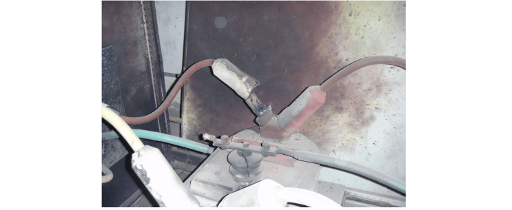
(2) Emergency Handling (Safety First)

  • Power Off: Immediately cut power for safety.
  • Inspect Secondary Circuit: Check for open circuits, minimize primary current, use insulation gear, and follow diagrams.

For secondary open circuits:

  • Assess Impact: Identify affected circuits, report to dispatch.
  • Reduce Load/Isolate: Transfer loads and de - energize if damaged.
  • Short - Circuit Secondary: Use approved materials; sparks mean downstream faults, no sparks mean upstream issues.

(3) Detection Techniques

  • Insulation Testing: Measure dielectric loss, capacitance to spot defects—good for aging assessment.
  • Infrared Thermography: My key tool! Detects loose connections/thermal issues quickly.
Conclusion
CTs are vital for grid reliability. Mastering their structure, principles, and fault handling ensures stability. Following guidelines, using detection tools, and acting on emergencies minimizes failures—securing a safer grid.
Felix Spark

Hey there! I'm an electrical engineer specializing in Failure and Maintenance. I've dedicated my career to ensuring the seamless operation of electrical systems. I excel at diagnosing complex electrical failures, from malfunctioning industrial motors to glitchy power distribution networks. Using state - of - the - art diagnostic tools and my in - depth knowledge, I pinpoint issues quickly. On this platform, I'm eager to share my insights, exchange ideas, and collaborate with fellow experts. Let's work together to enhance the reliability of electrical setups.

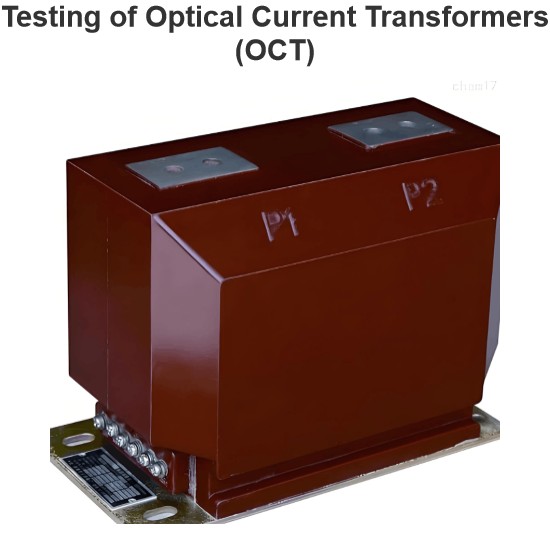
Testing of Optical Current Transformers (OCT)
With the development of modern economy and science and technology, photoelectric current transformers (PECTs) have fully transitioned from the trial operation stage to practical application. As a front - line testing personnel, I deeply feel their importance in the power system during daily work. I also realize the necessity of conducting in - depth research on their testing systems and calibration methods. This not only promotes the engineering application of PECTs but also enables the accurate
Oliver Watts
07/03/2025
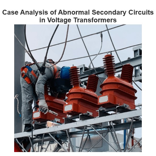
Case Analysis of Abnormal Secondary Circuits in Voltage Transformers
1. Fault SituationIn September 2023, as a front - line fault maintenance worker, I detected abnormal voltage on the 10kV Section I bus of a substation during monitoring duty and informed the operation and maintenance team. The monitoring system showed: U0 = 0 kV, Ua = 6.06 kV, Ub = 5.93 kV, Uc = 6.05 kV, Uab = 10.05 kV, Ubc = 5.94 kVMy team and I rushed to the site. We suspected the secondary air circuit breaker of the 10kV Section I bus voltage transformer was closed and found the U - phase fus
Felix Spark
07/02/2025
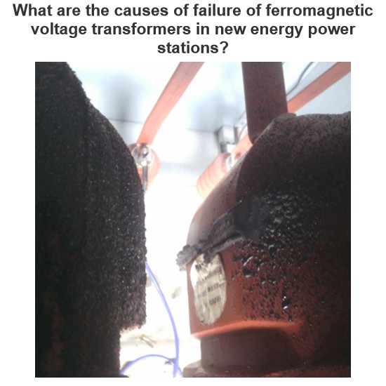
What are the causes of failure of ferromagnetic voltage transformers in new energy power stations?
By Felix, 15 Years in the Electrical IndustryHi everyone, I'm Felix, and I've been working in the electrical industry for 15 years.From early involvement in traditional substation commissioning and maintenance to now managing electrical system operations for multiple photovoltaic and wind power projects, one of the most frequently encountered devices I deal with is the Electromagnetic Voltage Transformer (PT).The other day, a shift operator at a new energy plant asked me:“We have an electr
Felix Spark
07/02/2025
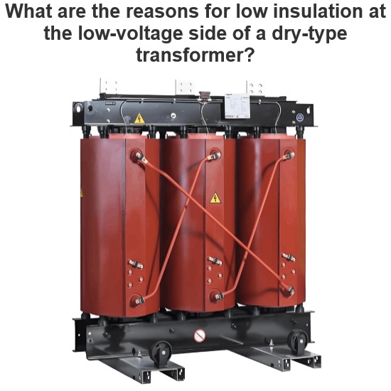
What are the reasons for low insulation at the low-voltage side of a dry-type transformer?
Hi everyone, I’m Felix, and I’ve been working in electrical equipment fault repair for 15 years.Over these years, I’ve traveled across factories, substations, and distribution rooms all over the country, troubleshooting and repairing all kinds of electrical equipment. Dry-type transformers are among the most common devices we deal with.Today, a friend asked me:“What does it mean when the low-voltage side of a dry-type transformer has low insulation resistance?”Great
Felix Spark
07/01/2025
Inquiry
Download
Experts Electrical is dedicated to serving the personnel in the global power industry.
Join Experts Electrical, not only can you discover power equipment and power knowledge, but also canhnd like - minded friends!