Testing of Optical Current Transformers (OCT)
Oliver Watts
07/03/2025

Topics
Hey! I'm Oliver Watts, an electrical engineer in Inspection and Testing. With years of hands - on experience, I ensure electrical systems meet top safety and performance standards. Using advanced gear, I conduct diverse tests, easily spotting issues in both large - scale industrial and small - scale commercial setups. I love teaming up, sharing knowledge, and keeping up with industry regs. Also, I'm skilled at data analysis with software. If you're into electrical inspection or just want to chat engineering, reach out. Let's connect and explore!
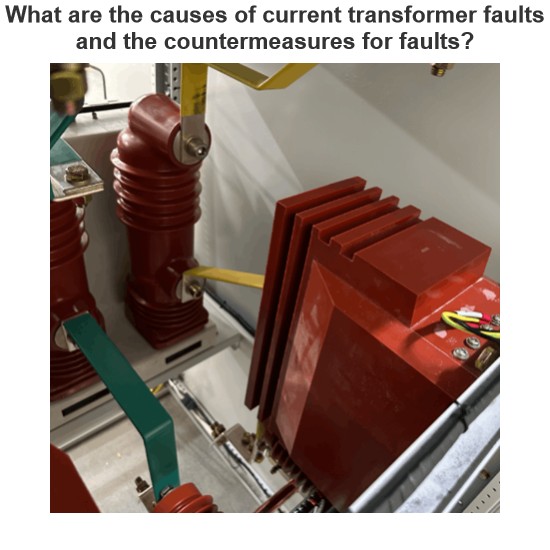
What are the causes of current transformer faults and the countermeasures for faults?
As a front - line maintenance technician, I deal with current transformers (CTs) daily. CTs convert high - magnitude primary current to low - magnitude secondary current for substation/line protection and measurement, operating in series long - term. However, they face faults from external (unbalanced loads, wrong wiring, etc.) and internal (insulation defects) issues. These faults, like secondary open - circuits or insulation breakdown, harm measurement accuracy, protection operation, and grid
Felix Spark
07/03/2025
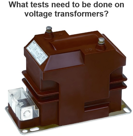
What tests need to be done on voltage transformers?
Practical Experience Sharing from an Electrical Engineer in the FieldBy Oliver, 8 Years in the Electrical IndustryHi everyone, I'm Oliver, and I've been working in the electrical industry for 8 years.From early involvement in substation commissioning and equipment inspection, to now managing the maintenance and fault analysis of entire power systems, one of the most frequently encountered devices in my work has been the voltage transformer (VT / PT).Recently, a friend who's just starting out ask
Oliver Watts
07/03/2025
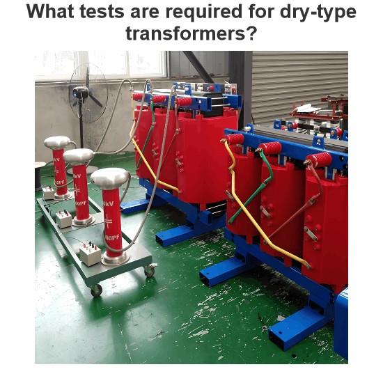
What tests are required for dry-type transformers?
1 Pre - commissioning InspectionAs a front - line tester, before formally commissioning a dry - type transformer, I need to carry out a comprehensive and systematic inspection. First, I conduct a visual inspection of the transformer body and its accessories, carefully checking for mechanical damage or deformation. Then, I check whether the leads of the high - and low - voltage windings are firmly connected and whether the bolt tightening torque meets the standard requirements (usually 40 - 60N&m
Oliver Watts
07/01/2025
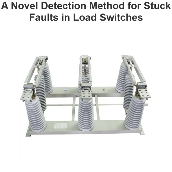
A Novel Detection Method for Stuck Faults in Load Switches
In recent years, as distribution automation advances, load switches see wider use in distribution lines. Yet, mechanical - failure - induced accidents are on the rise, burdening line operation and maintenance.Poor mechanical performance is the main cause of switch faults. Many scholars study large - scale switchgear operation, using methods like coil current detection, vibration signal analysis, switch travel testing, ultrasonic flaw detection, and infrared thermometry. Motor - current - based s
Oliver Watts
06/30/2025


