Protective Multiple Earthing (PME) – TN-C-S – (MEN) and PNB

Edwiin
05/16/2025
What is Protective Multiple Earth (PME)?
Protective Multiple Earth (PME) is a safety grounding method where the earth continuity conductor (ground wire) in a consumer’s premises is connected to both the local earthing system and the neutral conductor of the power supply. Also known as TN-C-S or Multiple Earther Neutral (MEN), this system ensures that if the neutral wire breaks, fault currents can still safely return to the source through the earth connection, minimizing the risk of electric shock and other hazards.
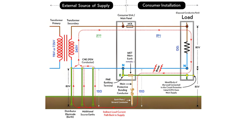
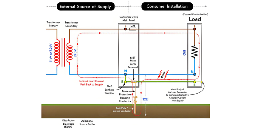
In the PME earthing system (illustrated below), the supply neutral serves a dual role: it provides protective earthing and acts as the neutral conductor. Additionally, the neutral conductor is grounded at multiple points on the supply side. The subsequent section of this article discusses the implications of an open-circuit PEN conductor (a break in the source neutral), including protective measures and potential risks associated with PME.
What is TN-C-S PME?
TN-C-S PME (Protective Multiple Earthing) is a specific configuration of an electrical distribution system where the external supply source is directly grounded at multiple points ("T" = Terre, French for "earth" or "ground"). On the consumer’s installation side, the conductive parts of equipment are connected via circuit protective cables (CPC) to both the supply neutral (N) and the grounding system.
The "C-S" designation indicates that the neutral (N) and protective earth (PE) conductors are combined (C) in the supply source’s network and separated (S) in the consumer’s installation.
Key Components of TN-C-S PME
- T: Terre ("earth/ground") — The system has a direct, independent ground connection separate from the supply conductors.
- N: Neutral — The return conductor for current in the electrical circuit.
- C: Combined — In the upstream supply network (e.g., from the transformer to the consumer’s main panel), the neutral (N) and protective earth (PE) conductors are merged into a single conductor called the PEN (Protective
- Earth Neutral) conductor.
- S: Separate — At the consumer’s main panel or distribution point, the PEN conductor splits into two independent conductors:
- Neutral (N): Carries the return current.
- Protective Earth (PE): Connects to equipment frames and ensures safety during faults.
How TN-C-S PME Works
- Upstream (Supply Side):
- The neutral and protective earth are combined as a PEN conductor, grounded at the source (e.g., transformer) and possibly at intermediate points (multiple earthing).
- Downstream (Consumer Side):
- At the consumer’s main panel, the PEN conductor is split into a separate neutral (N) and protective earth (PE).
- The PE conductor connects to all exposed conductive parts of equipment (e.g., metal casings) to safely divert fault currents to ground.
- The neutral (N) remains isolated from ground within the consumer’s installation (except for a single bonding point at the main panel to maintain potential stability).
Safety Benefits
- Fault Protection: In the event of a phase-to-metal fault, current flows through the PE conductor to ground, tripping the circuit breaker or fuse quickly.
- Neutral Breakage Safety: If the neutral conductor breaks upstream, the PEN/PE connection ensures that exposed metal parts remain at ground potential, reducing the risk of electric shock.
- Flexibility: Combines the simplicity of a combined neutral-earth system (TN-C) in the supply network with the safety of a separated system (TN-S) in the consumer’s premises, making it suitable for both urban grids and building installations.
This configuration balances cost efficiency in the supply network with enhanced safety in end-user environments, widely used in residential, commercial, and industrial settings.
What is PNB?
PNB, short for Protective Neutral Bonding, is a grounding method similar to the PME (Protective Multiple Earthing) system, but with a key difference: the Neutral-to-Earth (TN) connection is established on the consumer side (e.g., at the premises’ main panel) rather than at the power supply or distribution transformer.
In a TN-C-S system, PNB (Protective Neutral Bonding) refers to the configuration where the PEN (Protective Earth Neutral) or CNE (Combined Neutral Earth) conductors of individual consumers are connected to the power source (e.g., transformer) at only one point. This single bonding point ensures that the neutral and protective earth functions are combined upstream (from the transformer to the consumer’s main panel) and separated within the consumer’s installation (TN-C-S structure).
Key Considerations for PNB
- Earth Distance Requirement:The recommended distance between the grounding electrode and the consumer’s main panel (where the neutral-earth bond occurs) is less than 40 meters (≈130 ft.). To minimize voltage risks in the event of a neutral breakage, this distance should ideally be as short as possible, preferably adjacent to the main panel’s earth link bar.
- Safety Mechanism:By bonding the neutral to earth at the consumer’s premises, PNB helps stabilize the neutral’s potential and provides a backup path for fault currents if the upstream neutral conductor fails. This reduces the risk of exposed metal parts becoming live and causing electric shocks.
Difference from PME
While both PNB and PME involve neutral-earth bonding, PME typically involves multiple grounding points on the supply side (e.g., at the transformer and along the distribution network), whereas PNB focuses on a single bonding point at the consumer’s location within a TN-C-S framework.
PNB is designed to balance safety and simplicity in smaller-scale installations, ensuring compliance with electrical codes while minimizing the impact of neutral conductor faults in end-user environments.
Why and Where is the PME Earthing System Used?
Under the ESQCR (Electricity Safety, Quality and Continuity Regulations), consumers are prohibited from installing PEN conductors in HV/LV installations; this responsibility lies with the independent distribution network operator (DNO). This is because PME systems involve complex grounding configurations that require professional management to ensure safety and compliance.
Key Benefits of PME
The primary advantage of PME is its ability to mitigate risks during a broken neutral wire (open-circuit PEN conductor). If the neutral fails, the fault current can return to the supply source via the parallel earth path (created by multiple earthing points). This low-resistance pathway triggers protective devices (e.g., fuses, circuit breakers) to trip, as the high current due to low resistance melts the fuse or activates the breaker. Consequently, exposed metal parts remain at near-ground potential, eliminating the risk of electric shock from a broken neutral. Without PME, a neutral break would leave no return path, energizing the neutral wire and posing a severe shock hazard.
Applications of PME
Power supply companies and distributors often employ PME in rural or challenging terrains (e.g., mountainous areas) where:
- Individual low-resistance earthing for each building is costly or impractical.
- Obtaining suitable earth loop resistance from the transformer to consumer terminals is difficult.
- However, using PME requires written approval from relevant authorities due to its technical requirements and potential risks.
Conductor and Bonding Sizing for PME/PNB
For PME earthing, conductor sizing must adhere to BS 7671:2018+A2:2022 regulations:
- Earth conductor cross-sectional area: Follow 114.1 and 543.1.1.
- Calculations: Comply with Regulation 543.1.3 (fault current and duration).
- Protective conductor selection: Use Regulation 543.1.4 for sizing.
Potential Risks of PME Earthing
While PME enhances safety, it introduces specific hazards:
Raised Neutral Potential
If the neutral conductor breaks (common in rural overhead lines), all protective metalwork (e.g., equipment casings) bonded to the neutral can become energized. For example:
- A 5 kW load (12 Ω resistance) on a 240 V supply experiences a neutral break.
- Current returns via parallel earth paths (e.g., 12 Ω earth electrodes).
- Voltage splits across the load and earth paths: ~80 V appears on earthed metalwork, posing a shock risk.
Silent Faults
Unlike obvious faults, a broken neutral with PME may not trigger immediate protective action. The system can remain energized until someone touches the metalwork, leading to unexpected shocks.
Mitigation Requirements:
- Multiple Earthing: Neutral must be earthed at multiple points in the system.
- Low Earth Resistance: Each earth electrode’s resistance must not exceed 10 ohms.
- Individual Earth Rods: Recommended for each installation to minimize shared fault currents.
- Authority Approval: Formal approval is mandatory to ensure proper design and maintenance.
Conclusion
PME is a critical but regulated earthing method, ideal for areas with challenging earthing conditions. Its effectiveness relies on strict compliance with bonding, sizing, and maintenance standards to avoid risks like raised neutral potentials. Always consult qualified engineers and obtain regulatory approval when implementing PME systems.
Topics