What is Static Voltage Regulator?

Types of Static Voltage Regulator
The static voltage regulator is superior to electromechanical regulators in respect of the accuracy of control, response, reliability and maintenance. The static voltage regulator is mainly classified into two types. They are;
- Servo Type Voltage Regulator
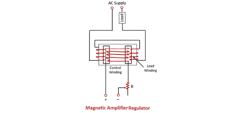
- Magnetic Amplifier Regulator
The types of static voltage regulator are described below in details;
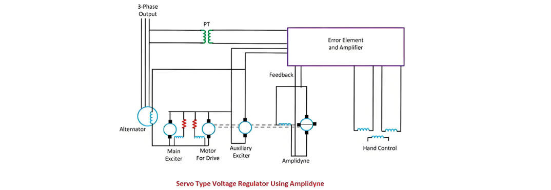
Servo Type Voltage Regulator
The main feature of the servo type voltage regulator is the use of the amplidyne. The amplidyne is a type of an electromechanical amplifier which amplifies the signal. The system contains the main exciter driven from the alternator shaft and an auxiliary exciter whose field winding is controlled by the amplidyne.
Both the auxiliary exciter and amplidyne are driven by a DC motor coupled to both the machines. The main exciter has a saturated magnetic circuit and hence has a rough output voltage. The armature of main and auxiliary exciter are connected in series, and this series combination excites the field winding of the alternator.
Working of Servo type Voltage Regulator
The potential transformer provides a signal which is proportional to the output signal of the alternator.The output terminals of the alternator are connected to the electronic amplifier. When the deviation occurs in the output voltage of the alternator, then the electronic amplifier sends the voltage to the amplidyne. The amplidyne output feeds the voltage to the amplidyne control field and hence alters the auxiliary exciter field. Thus, the auxiliary and the main exciter in series adjust the excitation current of the alternator.