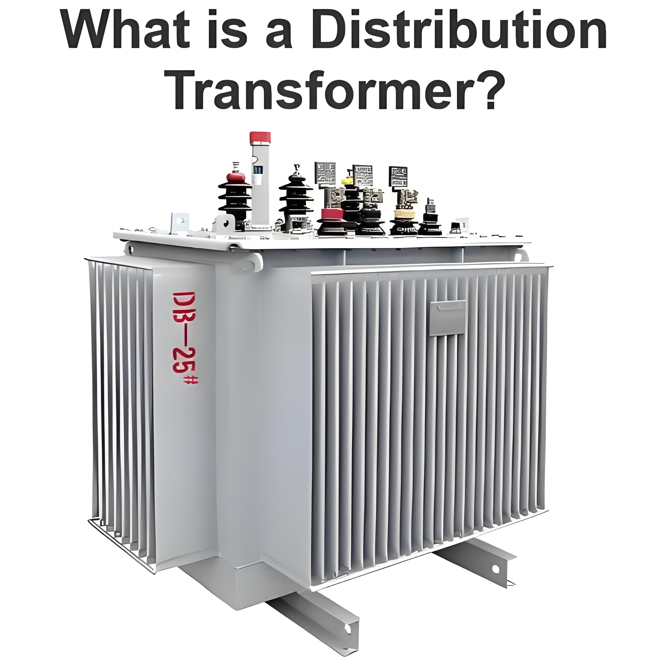
Search
English
English
Español
Français
العربية
Русский
Português
हिन्दी
বাংলা
Deutsch
日本語
Bahasa Indonesia
Italiano
RFQ
Home
Market
Solutions
Knowledge
Download the app
MENU
Home
Market
Solutions
Knowledge
English
English
Español
Français
العربية
Русский
Português
हिन्दी
বাংলা
Deutsch
日本語
Bahasa Indonesia
Italiano
Home
Knowledge
Transformer
Topics
Power Systems
Power system
Machines
circuit diagram
Measurement
Basic Electrical
Basic
Industrial circuit
Basic knowledge
Electric Power Knowledge
Transmission
Control
Motor
Transformer
Electric Motors
Protection
household circuit
Generation
Control Circuit
Circuit Theory
Resistance and Leakage Reactance or Impedance of Transformer
Leakage Reactance of TransformerAll the flux in transformer will not be able to link with both the primary and secondary windings. A small portion of flux will link either winding but not both. This portion of flux is called leakage flux. Due to this leakage flux in transformer, there will be a self-reactance in the concerned winding.This self-reactance of transformer is alternatively known as leakage reactance of transformer. This self-reactance associated with resistance of transformer is impe
Electrical4u
05/07/2024
Theory of Transformer on Load and No Load Operation
We have discussed about the theory of ideal transformer for better understanding of actual elementary theory of transformer. Now we will go through the practical aspects one by one of an electrical power transformer and try to draw vector diagram of transformer in every step. As we said that, in an ideal transformer; there are no core losses in transformer i.e. loss free core of transformer. But in practical transformer, there are hysteresis and eddy current losses in transformer core.Theory of
Electrical4u
05/06/2024
Transformer: What is it?
What is a Transformer?Atransformeris defined as apassive electrical devicethat transfers electrical energy from one circuit to another through the process ofelectromagnetic induction. It is most commonly used to increase (‘step up’) or decrease (‘step down’)voltagelevels between circuits.Working Principle of TransformerThe working principle of a transformer is very simple. Mutual induction between two or more windings (also known as coils) allows for electrical energy to be transferred between c
Electrical4u
05/04/2024
EMF Equation of Transformer
Emf Equation of TransformerEMF Equation of transformer can be established in a very easy way. Actually in electrical power transformer, one alternating electrical source is applied to the primary winding and due to this, magnetizing current flowing through the primary winding which produces alternating flux in the core of transformer. This flux links with both primary and secondary windings. As this flux is alternating in nature, there must be a rate of change of flux. According to Faraday’s law
Electrical4u
05/03/2024
Eddy Current Theory and Applications
What is Eddy Current According to Lenz’s law, a conducting loop when subjected to varying magnetic field gets an emf induced into it causing flow of current in a direction opposing the change causing it. The case goes similar to when instead of a conducting closed loop, the change in magnetic field through a conducting body, say a filament or a slab of magnetic material or non-magnetic material, causes currents to flow into its cross sections at appropriate closed paths. These currents are g
Electrical4u
05/02/2024
Efficiency of Transformer
Introduction of Efficiency of TransformerTransformers form the most important link between supply systems and load. Transformer’s efficiency directly affects its performance and aging. The transformer’s efficiency, in general, is in the range of 95 – 99 %. For large power transformers with very low losses, the efficiency can be as high as 99.7%. The input and output measurements of a transformer are not done under loaded conditions as the wattmeter readings inevitably suffer errors of 1 – 2%. So
Electrical4u
04/30/2024
Top 25 Important Transformer Interview Questions
1). Whatis a Transformer?Atransformeris a static device that converts electrical power from one circuit to another without affecting the frequency by stepping up (or)stepping down the voltage.2). What is the theory behind the transformer’s operation principle?The theory of mutual induction explains the operation of a transformer. A commonmagnetic flux connects two electrical circuits.3). What ismeant by a transformer’s rating?A transformer’s rating is the maximum power that may be extracted from
Hobo
03/12/2024
Vector Diagram of Transformer: An Essential Tool for Fault Analysis
A transformer is a device that transfers electrical energy from one circuit to another by electromagnetic induction. Transformers are widely used in power systems to step up or step down voltages, isolate circuits, and balance loads. Transformers can be classified into different types based on their construction, winding configuration, and vector group.A vector diagram of a transformer is a graphical representation of the phasor relationships between the primary and secondary voltages and curren
Electrical4u
03/12/2024
Individual DC Voltage Balance Control for Cascaded H-Bridge Electronic Power Transformer With Separated DC-Link Topology
In this paper, an overall individual dc voltage (including high-voltage and low-voltage dc-link voltages) balance strategy is proposed for the electronic power transformer with separated dc-link topology. The strategy adjusts active powers flowing through the isolation and output stages in different power modules to enhance the dc voltage balance capability. Through the strategy, the high-voltage and low-voltage dc-links can be well balanced when unbalance occurs among different power modules
IEEE Xplore
03/07/2024
A Two-Stage DC-DC Isolated Converter for Battery-Charging Applications
This paper proposes and analyzes a two-stage dc-dc isolated converter for electric vehicle charging applications, where high efficiency over a wide range of battery voltages is required. The proposed conversion circuit comprises a first two-output isolation stage with CLLC resonant structure and a second two-input buck regulator. The transformer of the first stage is designed such that its two output voltages correspond, ideally, to the minimum and maximum expected voltage to be supplied to th
IEEE Xplore
03/07/2024
1
2
···
14
15
16
17
18
19
20
21
Source professional electrical partners, experts, and explore smart grid & energy solutions.
Inquiry
Send Now
Download
Experts Electrical is dedicated to serving the personnel in the global power industry.
Join Experts Electrical, not only can you discover power equipment and power knowledge, but also canhnd like - minded friends!