• WDYZ-201 Zinc oxide arrester live tester
WDYZ-201 Zinc oxide arrester live tester
$6000.00
Model
MOAT-201
Basic info
Brand Wone
Model NO. WDYZ-201 Zinc oxide arrester live tester
Rated frequency 50Hz
Series WDYZ-201
Product Detail

Description

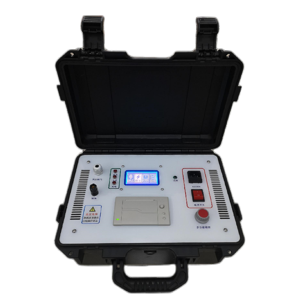
WDYZ-201 Zinc oxide arrester live tester is a special instrument for testing the electrical performance of zinc oxide arresters. 

This instrument is suitable for live or power failure detection of zinc oxide arresters of various voltage levels. Dangerous defects such as aging.

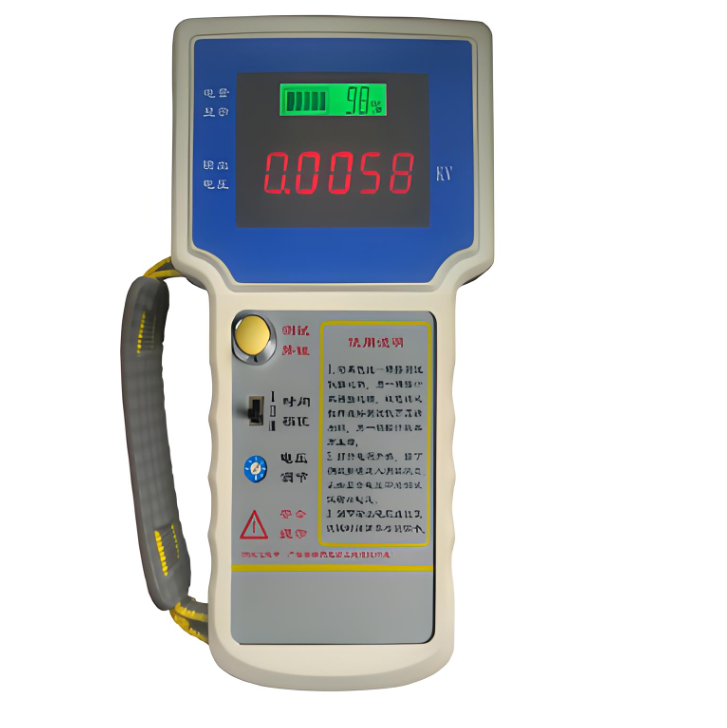
The instrument is simple to operate and easy to use. The whole measurement process is controlled by the man-machine interface. 

It can measure the full current, resistive current and its harmonics, power frequency reference voltage and its harmonics, active power and phase difference of zinc oxide arresters. 

Large screen Real waveforms of voltage and current can be displayed.

 The instrument uses digital waveform analysis technology, adopts software anti-interference methods such as harmonic analysis and digital filtering to make the measurement results accurate and stable, and can accurately analyze the content of the fundamental wave and the 3rd to 9th harmonics.

Specifications

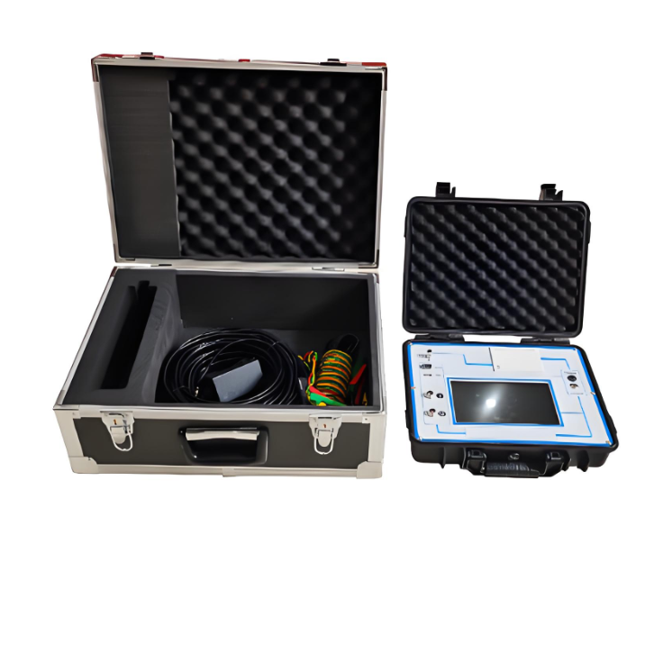
  • Power supply: internal lithium battery power supply or DC8.4V adapter

  •  Measuring range:

Leakage current: 0-20mA (expandable);

(Optional: Current clamp sensor 0-20mA.)

Voltage: 30-250V (expandable);

(Optional: Electric field strength input range: 30kV/m~300kV/m.)

Angle: 0-306º

Resistive current: 0-20mA (expandable);

Capacitive current: 0-20mA (expandable);

  •  Measurement accuracy:

Current: When the full current is >100μA: ±5% reading ±1 word;

Voltage: When the reference voltage signal is >30V: ±5% reading ±1 word.

  •  Measurement parameters:

Leakage current: full current waveform, fundamental RMS value, peak value.

Leakage Current Resistive Component: Waveform

1, 3, 5, 7, 9 valid values.

Positive peak Ir+ Negative peak Ir-.

Capacitive current fundamental.

Voltage: voltage waveform, voltage RMS.

Phase angle difference, power consumption.

  • Lithium battery parameters:

 Charging time > 2.5 hours

Continuous working time > 7 hours

Intermittent working time > 7×24 hours

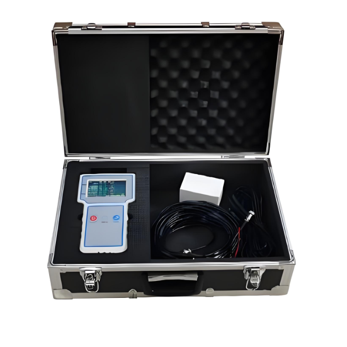
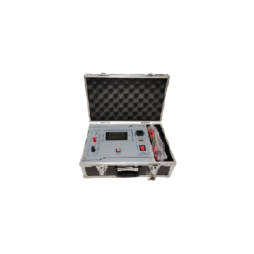
  • FCL size: host 42cm×34cm×18cm

  •  The weight of the whole box: 7.0kg for the host


Know your supplier
Wone
Main Categories
High voltage/Low voltage/Wire cable/Instrument meters/New energy/Tester/Production equipment/Generator/Electrical fittings/Integrated Electrical Equipment
Business Type
Design/Manufacture/Sales
Highest Annual Export (USD)
$50,000,000
Professional Experience
1 years
Workplace
65666m²m²
占位
占位
Related Products
Related Knowledges
Impact Analysis of Voltage Transformer Installation on Line Side vs. Load Side of Power Inlet Circuit Breaker for (ATS)
Automatic backup switching (ABTS) devices are core components ensuring the safe, reliable, and stable operation of factory power grids. Their startup logic strictly follows the dual criteria of "loss of voltage in the working power supply + no - current detection", effectively avoiding misjudgments caused by secondary disconnection of voltage transformers (VTs) or maloperations of ABTS due to secondary circuit faults of current transformers (CTs). The activation condition requires both "no volta
James
07/03/2025
What tests need to be done on voltage transformers?
Practical Experience Sharing from an Electrical Engineer in the FieldBy Oliver, 8 Years in the Electrical IndustryHi everyone, I'm Oliver, and I've been working in the electrical industry for 8 years.From early involvement in substation commissioning and equipment inspection, to now managing the maintenance and fault analysis of entire power systems, one of the most frequently encountered devices in my work has been the voltage transformer (VT / PT).Recently, a friend who's just starting out ask
Oliver Watts
07/03/2025
What are the development trends of voltage transformers?
By Echo, 12 Years in the Electrical IndustryHi everyone, I'm Echo, and I've been working in the electrical industry for 12 years.From early involvement in commissioning and maintenance of distribution rooms to later participation in electrical system design and equipment selection for large-scale projects, I’ve witnessed how voltage transformers have evolved — from traditional analog devices to intelligent, digital components.The other day, a new colleague from a power company asked
Echo
07/02/2025
Design of Electromagnetic Compatibility Performance for Electronic Voltage Transformers
With the rapid development of power systems, electronic voltage transformers (EVTs), as key measurement devices in power systems, their performance stability and reliability are crucial for the safe and stable operation of power systems. The electromagnetic compatibility (EMC) performance, as one of the core indicators of EVTs, is directly related to the ability of the device to work normally in complex electromagnetic environments and whether it will cause electromagnetic interference to other
Dyson
07/02/2025
Case Analysis of Abnormal Secondary Circuits in Voltage Transformers
1. Fault SituationIn September 2023, as a front - line fault maintenance worker, I detected abnormal voltage on the 10kV Section I bus of a substation during monitoring duty and informed the operation and maintenance team. The monitoring system showed: U0 = 0 kV, Ua = 6.06 kV, Ub = 5.93 kV, Uc = 6.05 kV, Uab = 10.05 kV, Ubc = 5.94 kVMy team and I rushed to the site. We suspected the secondary air circuit breaker of the 10kV Section I bus voltage transformer was closed and found the U - phase fus
Felix Spark
07/02/2025
What are the causes of failure of ferromagnetic voltage transformers in new energy power stations?
By Felix, 15 Years in the Electrical IndustryHi everyone, I'm Felix, and I've been working in the electrical industry for 15 years.From early involvement in traditional substation commissioning and maintenance to now managing electrical system operations for multiple photovoltaic and wind power projects, one of the most frequently encountered devices I deal with is the Electromagnetic Voltage Transformer (PT).The other day, a shift operator at a new energy plant asked me:“We have an electr
Felix Spark
07/02/2025
×
Inquiry
Download
Experts Electrical is dedicated to serving the personnel in the global power industry.
Join Experts Electrical, not only can you discover power equipment and power knowledge, but also canhnd like - minded friends!