| Brand | Wone |
| Model NO. | New Silicon Steel Sheet Automatic Cut to Length Line Machine for Transformer Lamination Core with Motor PLCS Industrial Use |
| Shearing thickness | 0.23-0.35mm |
| Shearing width | 60-640mm |
| Shearing length | 600-3500mm |
| Weight of material | >3000kg |
| Series | SKJ |
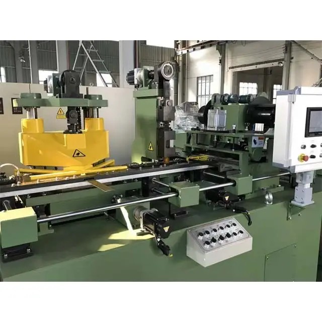
Features
lThe high accuracy of sheet feeding and cutting is guaranteed by precise photoelectric encoder, SIEMENS AC servo drive system and SIMOTION Motion controller.
lCentral positioning for whole line guide width adjustment is controlled by computer.
lAdoption of graphic operation terminal with human-machine menu and colored processing pattern display enables operators to complete lamination shapes confirmation and parameters input through the touch screen.
lCompensation and achieves rapid adjustment of cutting length.
lCutting function and can cut step-lap lamination automatically.
lPreset number of sheets can be done automatically.Punching and shearing are driven by high dynamic servomotors, efficient with low noise.
lAutomatic stacking is adopted to stack silicon steel sheets from largest to smallest sizes or from smallest to largest sizes.
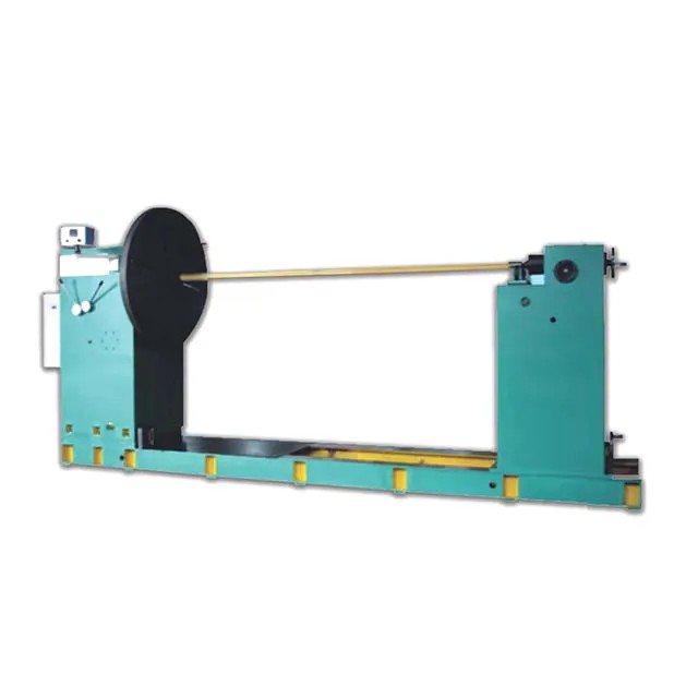
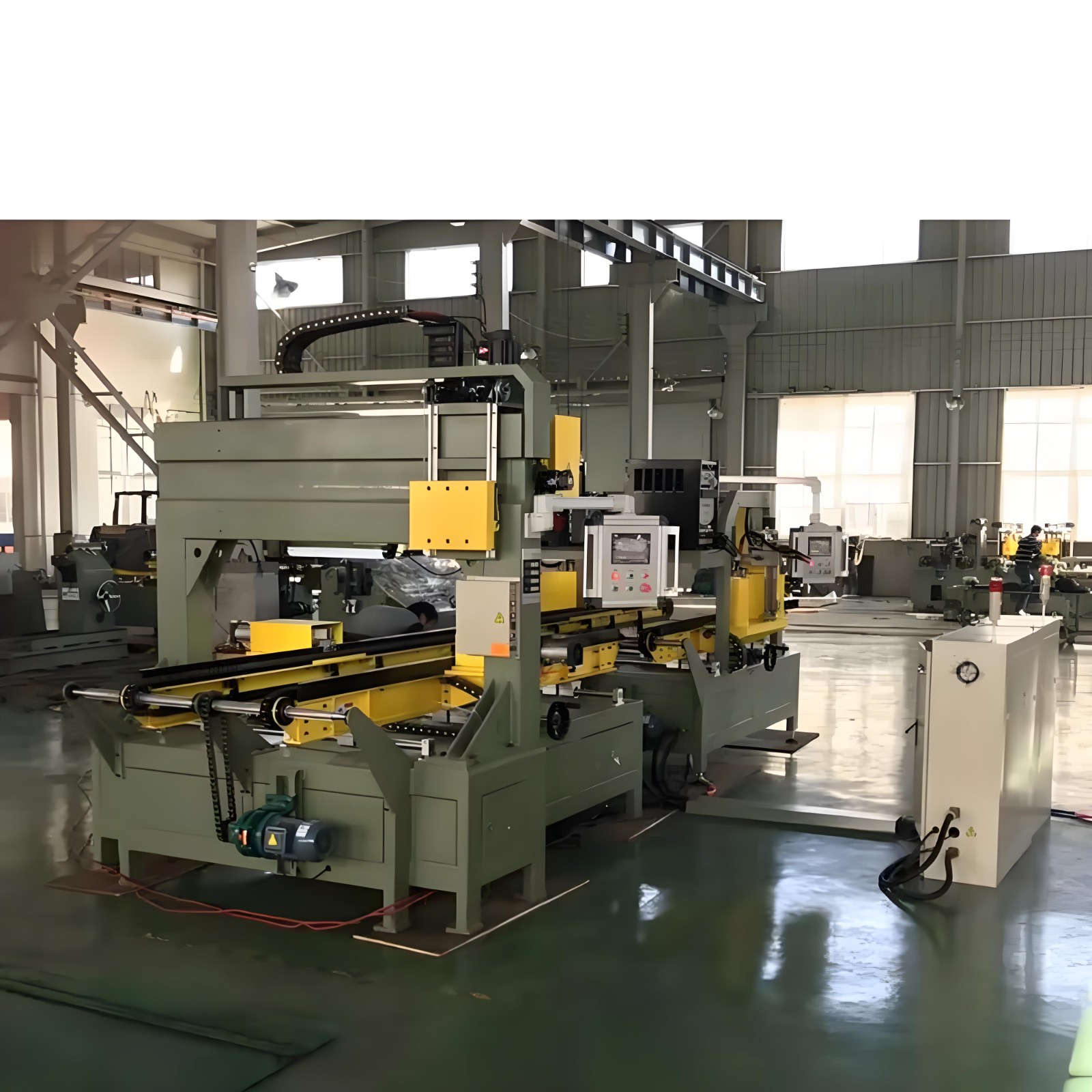
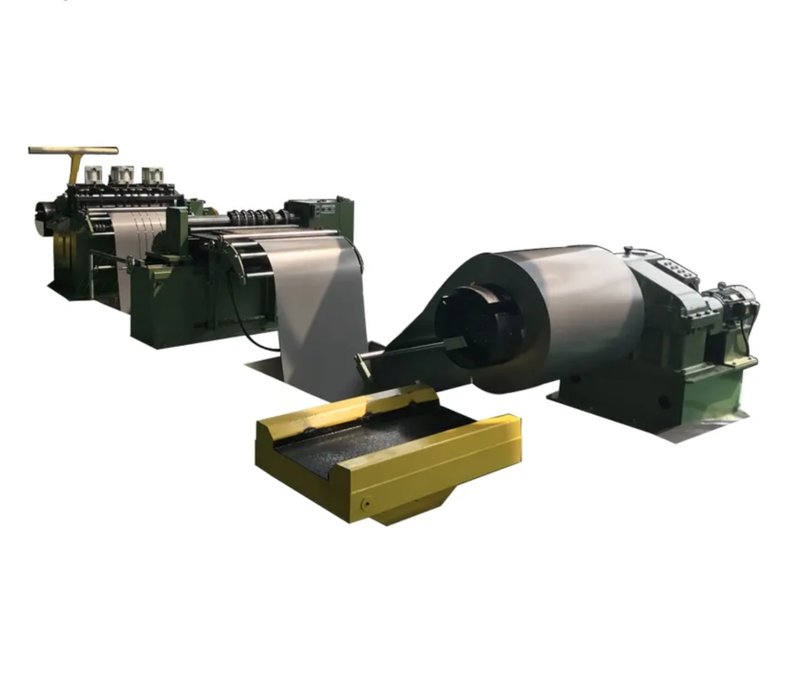
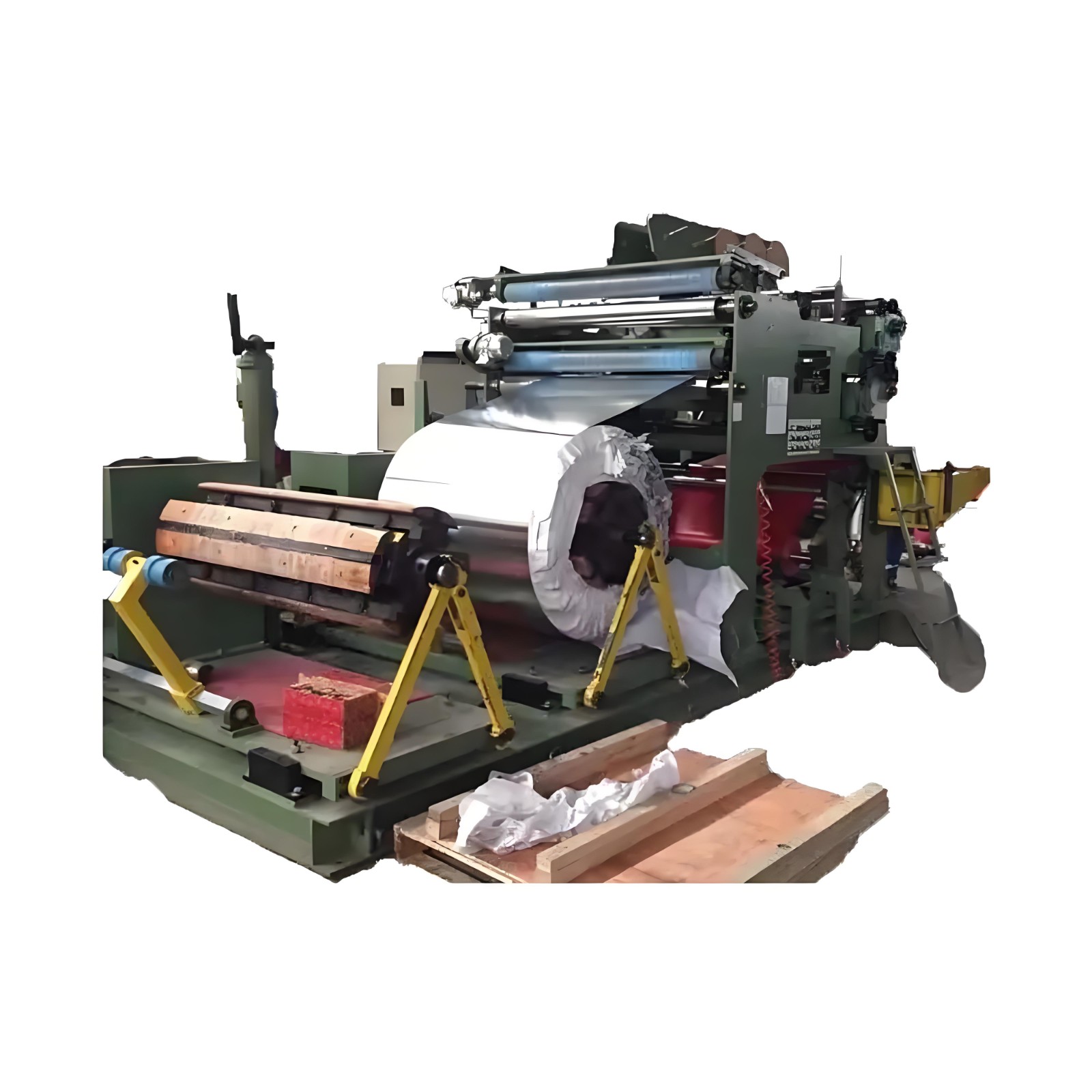
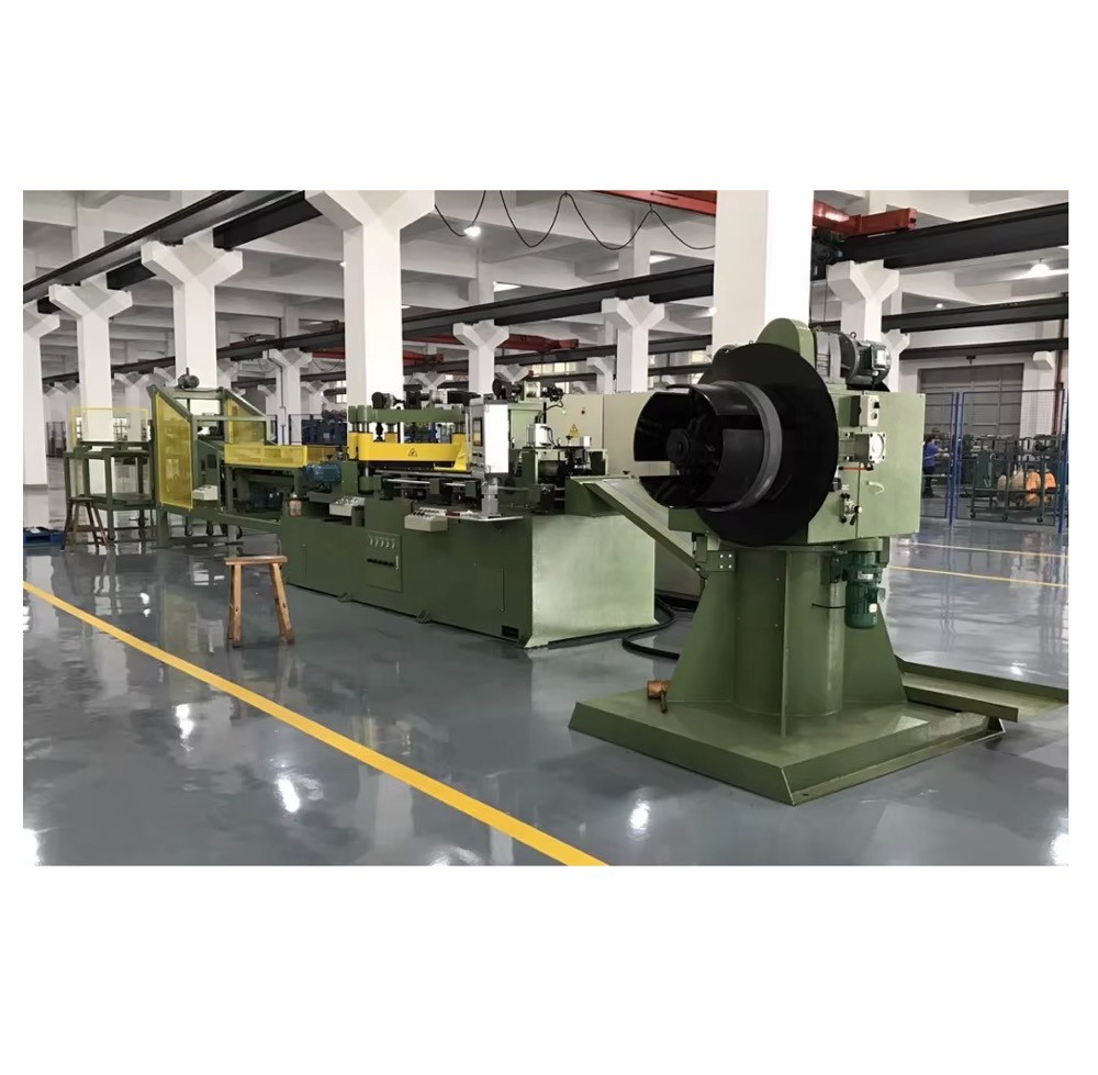
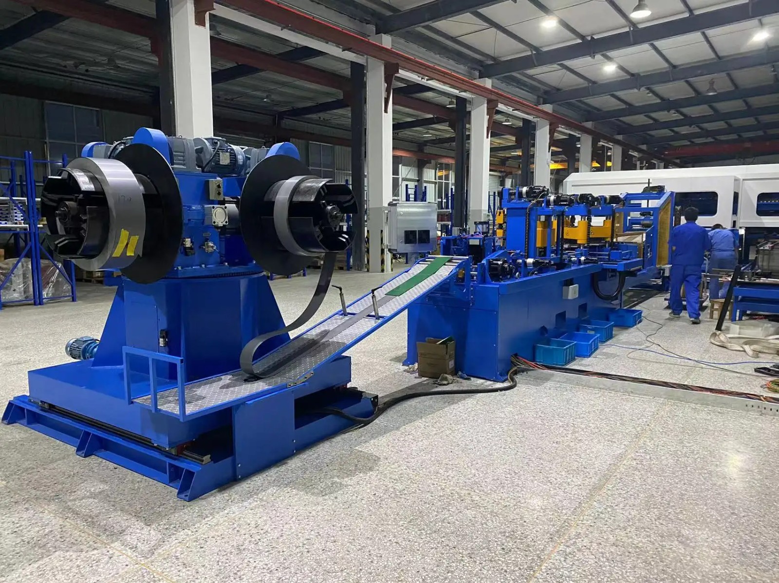
Composition
(1). Double head decoiler (2). Sheet guiding device (3). Sheet feeder
(4). Punching unit (5). Shearing unit (6). Discharge table (7). Diverting mechanism
(8). Stacking trolley (9). Control cabinet (10). Operating console
Specifications
Item |
SKJ450 |
SKJ600 |
Shearing thickness |
0.23-0.35mm |
0.23-0.35mm |
Shearing width |
40-450mm |
60-640mm |
Shearing length |
340-2000mm |
600-3500mm |
Punching aperture |
customized |
customized |
Feeding speed |
240m/min |
240m/min |
Shear rate (length 1000 mm) |
50 piece/min |
50 piece/min |
Shearing accuracy |
±0.1 |
±0.1 |
Shearing angel accuracy |
±0.01° |
±0.01° |
Shearing burrs |
≤0.02mm |
≤0.02mm |
Outer diameter of coiled material |
No more thanφ1000mm |
No more thanφ1000mm |
Coil I.D. |
φ500mm |
φ500mm |
Weight of material |
No more than 1500kg |
No more than 3000kg |
Spindle telescoping range of decoiler |
φ470-φ520mm |
φ470-φ520mm |
Carried material table height |
No more than 200 mm |
No more than 300 mm |
Discharge direction |
Transverse |
Transverse |