• Circuit Breaker Operating Mechanism
Circuit Breaker Operating Mechanism
discuss personally
Model
CBOM-12
Basic info
Brand MV Switch Accessories
Model NO. Circuit Breaker Operating Mechanism
Rated voltage 12kV
Series CBOM
Product Detail

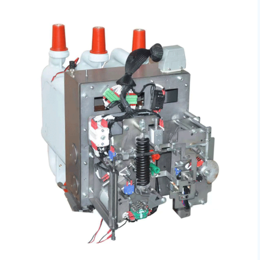
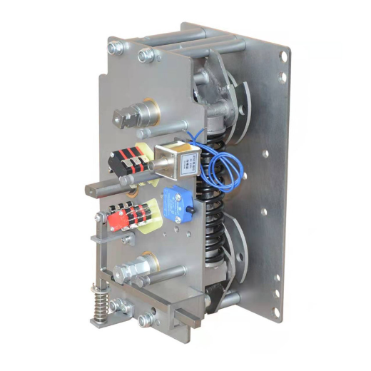
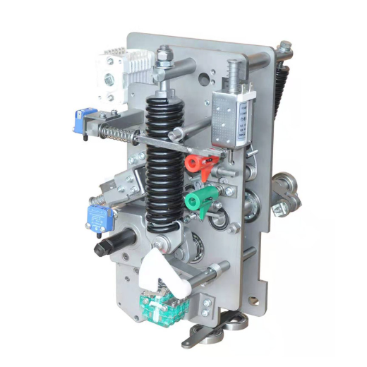
Overview This spring operated circuit breaker mechanism is suitable for use in 12kV AC metal-enclosed switchgear with isolating mechanism.The mechanism adopts the mode of tension spring over-center control to realize the transmission of three working positions of closing-opening-grounding.The rotation angle of the main shaft of the fitting body of the mechanism is 45°~80°.The mechanism opening spring and cushion oil cup sealing box are designed in front, which is convenient for debugging, testing and maintenance.

Operation Specification

Tap-off ground: close the cable chamber door, press the switch-off button, or press the electric switch-off button to open the circuit breaker, and move the unlocking lever to the right

At the position of "grounding ", insert the crank into the grounding operation hole, turn the crank clockwise for 15 circles until the crank is still, and pull out the crank.Close and isolate: move the unlocking lever to the "isolated" position to the left, insert the handle into the isolation operation hole, first turn the handle clockwise by 1/10 circles, then turn the handle counterclockwise by 17.5 circles until the handle is still, and pull out the handle.

Unlock: Move the unlock lever to the right to the "Unlock" position.

Closing the circuit breaker: insert the crank into the energy storage hole, swing the crank clockwise, or press the electric energy storage button. After hearing the "Pa" sound, the energy storage is in place. Press the closing button or the electric closing button to close the circuit breaker.

Power-off operation: press the opening button or press the electric opening button to open the circuit breaker

Overhaul:

Separation: move the unlocking handle to the "isolation" position to the left, insert the handle into the isolation operation hole, and turn the handle clockwise for 17.5 circles until the handle does not move and pull out the handle.

Close the grounding: move the unlocking handle to the right to the "grounding" position, insert the crank into the grounding operation hole, first turn the crank clockwise for 110 circles, then turn the crank counterclockwise for 15 circles until the crank is not moved, and pull out the crank to unlock: move the unlocking handle to the left to the "unlocking" position.

Closing the circuit breaker: insert the crank into the energy storage hole, turn the crank clockwise, or press the electric energy storage button. After the sound of "crack" is heard, the energy storage is in place. Press the closing button or the electric closing button to close the circuit breaker.Open the cable room for maintenance.
Outline installation dimension drawing of mechanism:
operhi-circuit-breaker-operating-mechanism-1.jpg

Know your supplier
MV Switch Accessories
VoltEdge Solutions​​ specializes in manufacturing premium ​​MV switchgear accessories​​ for global power distribution systems. Our product range includes circuit breaker modules, disconnector spares, and surge arrestors, engineered for ​​24kV+ substations​​ and renewable energy plants. With ISO-certified production and 24/7 technical support, we ensure ​​reliability, compliance​​ with IEC standards, and rapid global supply.
Main Categories
Switchgear parts
Business Type
Sales
Highest Annual Export (USD)
$300000000
Professional Experience
1 years
Workplace
1000m²
占位
占位
Related Products
Related Knowledges
What should be noted when selecting and installing GIS voltage transformers?
In power systems, voltage transformers in GIS (Gas Insulated Switchgear) play a crucial role in voltage measurement and relay protection. Selecting the right model and installing it correctly is vital for the stable operation of the equipment. The following points should be noted regarding selection and installation.I. Key Points for Selection(1) Matching Rated ParametersVoltage Level: It must be consistent with the voltage level of the GIS system. For example, 110kV and 220kV GIS systems requir
James
07/08/2025
What are the causes of the breakdown and burning of the 35 kV GIS voltage transformer?
1. Accident Overview1.1 Structure and Connection of 35kV GIS Switchgear Voltage TransformerThe ZX2 gas-insulated double-bus switchgear, manufactured in March 2011 and officially put into operation in July 2012, is configured with two groups of bus voltage transformers (PTs) for each bus section. The two PT groups of the same bus section are designed in one switchgear cabinet with a width of 600 mm. The three-phase PTs are arranged in a triangular formation at the bottom of the cabinet.The PTs ar
Felix Spark
07/08/2025
What Are the Steps for Error Testing GIS Voltage Transformers?
Hey everyone, I'm Oliver, and I've been working with current transformers (CTs) and voltage transformers (VTs) for 8 years.From assisting my mentor on site to leading high-voltage testing teams and conducting error calibrations independently, I’ve dealt with all kinds of instrument transformers — especially those used in GIS systems. The error test for voltage transformers is something I perform regularly.A few days ago, a friend asked me:“Oliver, how exactly do you perform an
Oliver Watts
07/08/2025
An GIS Equipment Explosion Accident Caused by PT Secondary Wiring Errors
1. Accident OverviewA newly - built 110kV substation’s GIS exploded during commissioning due to a PT secondary circuit short - circuit. Though the cause was simple, consequences were severe, warranting reflection.2. Accident ProcessOn the power - transmission day:The upper - level power supply charged the 110kV GIS (a combined appliance).20s after closing the incoming switch and first live - impacting the 110kV bus, white smoke emerged between the PT compartment and control cabinet.Within
Felix Spark
07/08/2025
Operation Method for PT Resonance in 500kV GIS Switching Station
1. Causes of ResonanceA 500kV GIS switching station is designed following the principle of “primary equipment intelligence and secondary equipment networking”. The PT high - voltage side has no disconnector and is directly connected to the bus GIS. Through the analysis of fault recording diagrams, when the 5021 circuit breaker opens, the fracture capacitance and PT form a series circuit. Moreover, the bus voltage, after being paralleled by the PT inductance, shows inductive character
James
07/08/2025
What to Pay Attention to When Selecting and Installing GIS Current Transformers?
Hi everyone, I'm James, and I've been working with current transformers (CTs) for 10 years. Today, I’ll talk about what you need to watch out for when selecting and installing GIS current transformers.Part 1: Key Considerations During Selection1. Accuracy ClassProtection-grade CTs: Used for relay protection — focus on overload capacity and transient response.Metering-grade CTs: Used for billing purposes — require high accuracy, usually 0.2S or 0.5S class.2. Rated Primary Curren
James
07/07/2025
×
Inquiry
Download
Experts Electrical is dedicated to serving the personnel in the global power industry.
Join Experts Electrical, not only can you discover power equipment and power knowledge, but also canhnd like - minded friends!