• 72.5kV 126kV 145kV 252kV HV SF6 Circuit Breaker
72.5kV 126kV 145kV 252kV HV SF6 Circuit Breaker
discuss personally
Model
LW35-252/4000-50
LW35-252/3150-50
LW35-145/4000-50
LW35-145/3150-50
LW35-126/4000-50
LW35-126/3150-50
LW35-72.5/4000-63
LW35-72.5/3150-50
Basic info
Brand Wone
Model NO. 72.5KV 126KV 145KV 252KV SF6 Circuit Breaker
Rated voltage 252kV
Rated normal current 4000A
Series LW35
Product Detail

Description

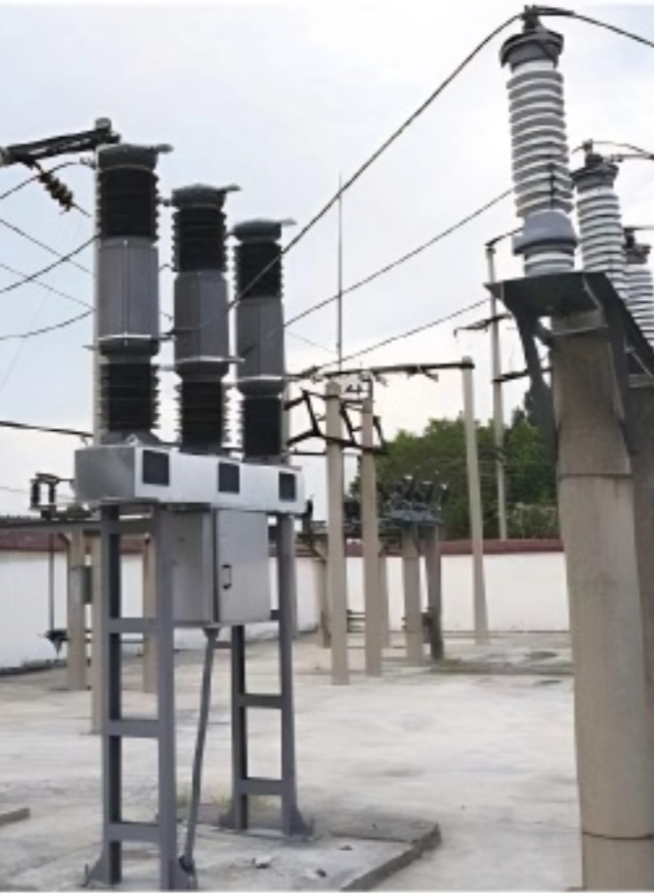
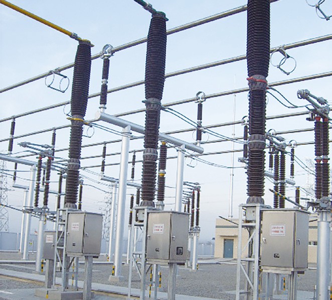
LW35 serial circuit breakers, including LW35-72.5, LW35-126, LW35-145 and LW35-252 products, are designed with self-energizing principle that arc generated in the interrupter is distinguished at a specified time with a part of energy produced by the arc itself. They are used for making and breaking normal current, fault current and switching lines to realize the operation (three-pole opening & closing operation and fast automatic-reclosing operation),  control and protection of power system.


Main Features


  • Less consumption of SF6 gas, benefitial for environmental protection. When other kinds of circuit breaker at 0.6 MPa must be filled with SF6 of 27 kg/set, this kind of circuit breaker only need 19.3 kg/set.

  • Dynamic sealing system adopts advanced Glyd-ring and Step seal to reduce starting friction and prevent leakage.

  • Adopt imported control valve of stable performance and anti-slow-opening function in case of pressure loss.

  • Two sets of independent opening control circuit are adopted in hydraulic mechanism with two sets of relay protection to enhance service reliability.


Technical parameter:


LW35.png

What are the purity requirements for SF6 gas in the interrupter of a tank circuit breaker?

  • SF₆ Gas Purity: The purity of SF₆ gas is generally required to be 99.8% or higher. High-purity SF₆ gas ensures its excellent insulating and arc-quenching performance. The presence of impurities can reduce the insulation strength and arc-quenching capability of SF₆ gas. For example, contaminants such as moisture and air can affect the ionization process and the cooling effect of the arc.

  • Toxic and Harmful Substances: When SF₆ gas contains a significant amount of impurities, it may produce more toxic and harmful substances under the influence of the arc, posing greater risks to both equipment and human health.


Know your supplier
Wone
Main Categories
High voltage/Low voltage/Wire cable/Instrument meters/New energy/Tester/Production equipment/Generator/Electrical fittings/Integrated Electrical Equipment
Business Type
Design/Manufacture/Sales
Highest Annual Export (USD)
$50,000,000
Professional Experience
1 years
Workplace
65666m²m²
占位
占位
Related Products
Related Knowledges
The design of the three-purpose grounding transformer
Underground Power Cable Transmission LinesDirect - buried power cable lines have large ground - distributed capacitance, causing high single - phase - to - ground short - circuit capacitive current. For 10 kV lines, if this current exceeds 10 A, arcs hardly self - extinguish, risking arc overvoltage and endangering line equipment. Arc extinction is thus necessary. With a Dyn - connected main transformer, an arc - suppression coil on the secondary neutral point suffices. For Yd - connected ones,
Dyson
06/12/2025
Failure Analysis and Design Optimization of Conventional Grounding Transformers
I. Core Cause of Damage: Electrodynamic Impact (Complying with GB/T 1094.5 / IEC 60076-5)The direct cause of high-voltage winding end collapse is the instantaneous electrodynamic impact induced by short-circuit current. When a single-phase grounding fault occurs in the system (such as lightning overvoltage, insulation breakdown, etc.), the grounding transformer, as the fault current path, withstands high-amplitude and steep-rise-rate short-circuit currents. According to Ampère's force law
Felix Spark
06/12/2025
Analysis of Grounding Transformer Operational Behavior Under System Single-Phase-to-Ground Fault Conditions
1 Theoretical AnalysisIn distribution networks, grounding transformers serve two key roles: powering low - voltage loads and connecting arc - suppression coils at neutrals for grounding protection. Grounding faults, the most common distribution network fault, heavily impact transformers’ operating characteristics, causing sharp changes in electromagnetic parameters and status.To study transformers’ dynamic behaviors under single - phase grounding faults, build this model: Assume a tr
Felix Spark
06/12/2025
Design Calculations for Neutral Grounding Schemes and Grounding Transformer Sizing in Utility-Scale Solar PV Plants
1 Classification of Neutral Grounding Methods for Solar Photovoltaic Power StationsInfluenced by differences in voltage levels and grid structures across regions, the neutral grounding methods of power systems are mainly categorized into non-effective grounding and effective grounding. Non-effective grounding includes neutral grounding via arc suppression coils and neutral ungrounded systems, while effective grounding comprises neutral solid grounding and neutral grounding via resistors. The sel
Dyson
06/12/2025
Zero-Sequence Impedance Characterization of Dry-Type Grounding Transformer with ZN Connection
In a neutral-insulated three-phase power system, an earthing transformer provides an artificial neutral point, which can be solidly earthed or earthed via reactors/arc suppression coils. The ZNyn11 connection is typical, where zero-sequence magnetomotive forces in the inner/outer half-windings of the same core column cancel out, balancing fault currents in series windings and minimizing zero-sequence leakage flux/impedance.Zero-sequence impedance is critical: it determines fault current magnitud
Dyson
06/12/2025
Case Analysis on Maloperation of Grounding Transformer Overcurrent Protection Relay
The neutral grounding mode refers to the connection between the power system neutral point and ground. In China's 35 kV and below systems, common methods include ungrounded neutral, arc-suppression coil grounding, and small-resistance grounding. The ungrounded mode is widely used as it allows short-term operation during single-phase grounding faults, while small-resistance grounding has become mainstream for its fast fault removal and overvoltage limitation. Many substations install grounding tr
Felix Spark
06/12/2025
×
Inquiry
Download
Experts Electrical is dedicated to serving the personnel in the global power industry.
Join Experts Electrical, not only can you discover power equipment and power knowledge, but also canhnd like - minded friends!
商品视频播放