Underground Power Cable Transmission Lines
Direct - buried power cable lines have large ground - distributed capacitance, causing high single - phase - to - ground short - circuit capacitive current. For 10 kV lines, if this current exceeds 10 A, arcs hardly self - extinguish, risking arc overvoltage and endangering line equipment. Arc extinction is thus necessary. With a Dyn - connected main transformer, an arc - suppression coil on the secondary neutral point suffices. For Yd - connected ones, an artificial neutral point (provided by a grounding transformer) is needed.
1 Grounding Transformers
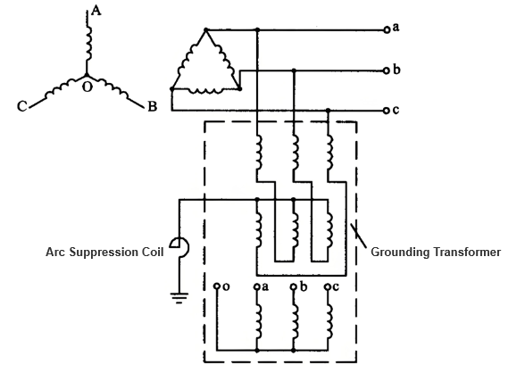
A grounding transformer serves two purposes: its primary side acts as an artificial neutral point (grounded via an arc - suppression coil to supply inductive current for arc extinction), and the secondary side powers the substation. Arc - suppression coils are essential companions. As shown in Figure 1, its primary side uses a Z - connection (to reduce zero - sequence impedance and enhance compensation) to derive a neutral point. The coil, with adjustable air gaps/turns, balances capacitive current (to below 5 A) for grounding and arc extinction.
Due to unequal primary - secondary capacities, grounding transformers are 15% lighter than same - capacity ordinary power transformers.
2 Three - purpose Grounding Transformer
To enhance power line safety and reliability, overseas applications widely use a Z - connected neutral coupler (no secondary side) paired with an arc - suppression coil for arc extinction. However, such couplers (for YNd/Yd - connected main transformers) only serve as artificial neutrals, failing to supply 400V low - voltage power. Thus, an extra station - use power transformer is needed, increasing costs, space, and causing high losses/poor reliability.
To address this, Kunming Transformer Factory developed the three - purpose grounding transformer (SJDX - 630/160/10). It integrates a Z - connected neutral coupler (no secondary winding), an arc - suppression coil, and a station - use power transformer. Its core structure is shown in Figure 2.
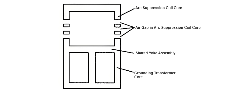
This three - purpose grounding transformer is mounted on a five - limb conjugate core. The primary (with tap changers) and secondary windings of the three - phase grounding transformer are wound on three limbs (lower part in Fig. 2), while the arc - suppression coil is on the other two (upper part in Fig. 2). Placing the lighter arc - suppression coil on top eases air - gap adjustment but requires reinforced fixing. Reversing the layout uses the heavier transformer to stabilize the coil, reducing vibration at the cost of coil installation and air - gap adjustment convenience. This design streamlines structure, saves materials, cuts losses, ensures good compatibility, and enables automated arc - extinction compensation via microcomputer control.