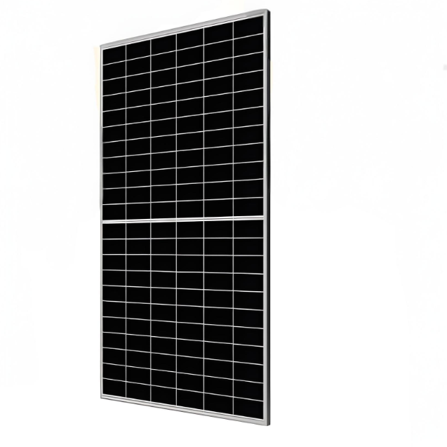
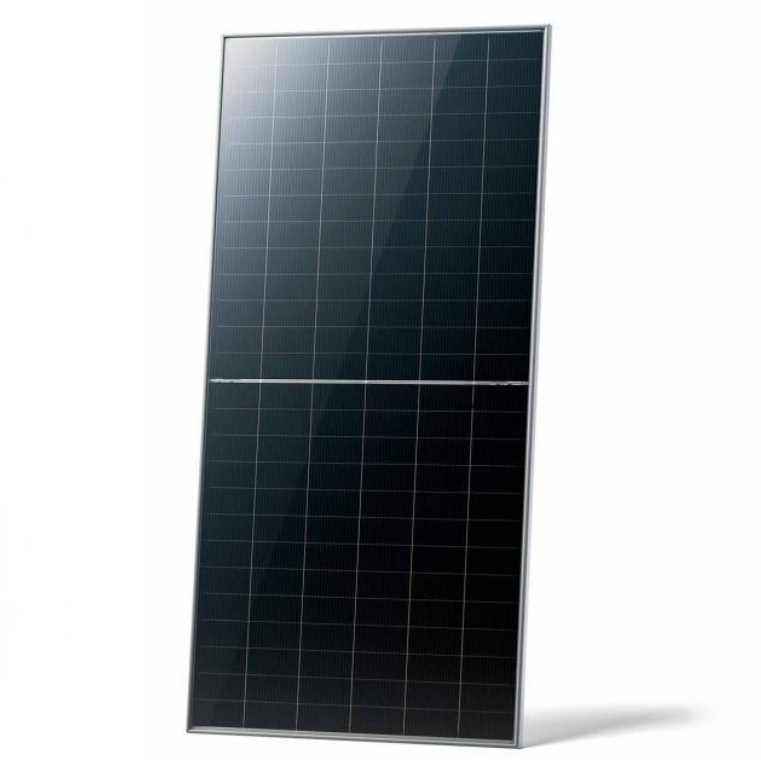
690 W - 720 W High-power N-type TOPCON bifacial modules
discuss personally
Model
| Brand | Wone |
| Model NO. | 690 W - 720 W High-power N-type TOPCON bifacial modules |
| Power Bifaciality | 80% |
| Max. System Voltage | 1500V (IEC) |
| Max. Series Fuse Rating | 35 A |
| Module Fire Performance | CLASS C |
| Max. power of the module | 700W |
| Max. efficiency of Module | 22.2% |
| Series | N-type Bifacial TOPCon Technology |
Features
Module power up to 720 W Module efficiency up to 23.2 %.
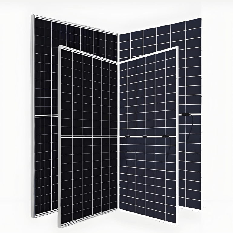
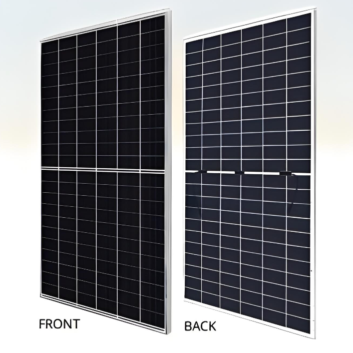
Up to 85% Power Bifaciality, more power from the back side.
Excellent anti-LeTID & anti-PID performance. Low power degradation, high energy yield.
Lower temperature coefficient (Pmax): -0.29%/°C, increases energy yield in hot climate.
Lower LCOE & system cost.
Standard
Tested up to ice ball of 35 mm diameter according to IEC 61215 standard.
Minimizes micro-crack impacts.
Heavy snow load up to 5400 Pa, wind load up to 2400 Pa*.
Engineering drawing(mm)

CS7N-695TB-AG / I-V gurves

Electrical date/STC*

Electrical date/NMOT*

Electrical date

Temperature charactheristics

What is bifacial gain in PV modules?
Definition:
Bifacial gain refers to the additional electricity generation of bifacial photovoltaic modules after they receive extra light from the environment on their back sides. This additional electricity generation is in comparison to monofacial photovoltaic modules, as monofacial photovoltaic modules can only absorb the direct light on their front sides.
Working Principle:
Front-side Absorption: Similar to single-sided modules, the front side of bifacial modules can absorb direct sunlight.
Back-side Absorption: The back side of bifacial modules is also capable of absorbing various kinds of light from the environment, including light reflected from the ground, light reflected from surrounding objects, and scattered light from the sky.
Gain Range:
Depending on different environmental conditions and installation methods, the gain of bifacial photovoltaic modules can range from 4% to 30%. The specific gain value depends on the influencing factors mentioned above.