• 580-605 Watt mono-facial module with Tunnel Oxide Passivating Contacts (TOPcon) technology
  • 580-605 Watt mono-facial module with Tunnel Oxide Passivating Contacts (TOPcon) technology
  • 580-605 Watt mono-facial module with Tunnel Oxide Passivating Contacts (TOPcon) technology
580-605 Watt mono-facial module with Tunnel Oxide Passivating Contacts (TOPcon) technology
discuss personally
Model
SP-605-V
SP-600-V
SP-595-V
SP-590-V
SP-585-V
SP-580-V
Basic info
Brand Wone
Model NO. 580-605Watt MONO-FACIAL MODULE
Maximum Power 605Wp
Series 72HL4-(V)
Product Detail

Certification

  • IEC61215:2021 / IEC61730:2023 ·

  •  IEC61701 / IEC62716 / IEC60068 / IEC62804 · 

  • ISO9001:2015: Quality Management System ·

  • ISO14001:2015: Environment Management System ·

  •  ISO45001:2018: Occupational health and safety management systems.

Features

  • N-type modules with Tunnel Oxide Passivating Contacts (TOPcon) technology offer lower LID/LeTID degradation and better low light performance.

  • N-type modules with JinkoSolar's HOT 3.0 technology offer better reliability and efficiency.

  • High salt mist and ammonia resistance.

  • Certified to withstand: 5400 Pa front side max static test load 2400 Pa rear side max static test load.

  • Better light trapping and current collection to improve module power output and reliability.

  • Minimizes the chance of degradation caused by PID phenomena through optimization of cell production technology and material control.


image.png


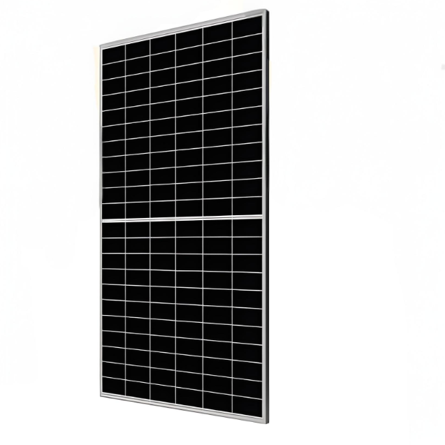
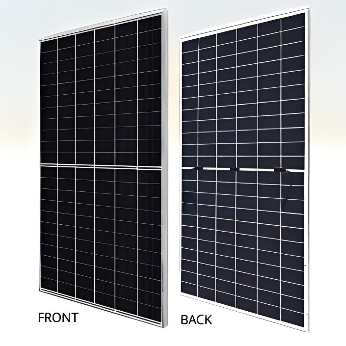
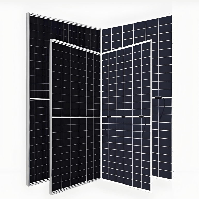
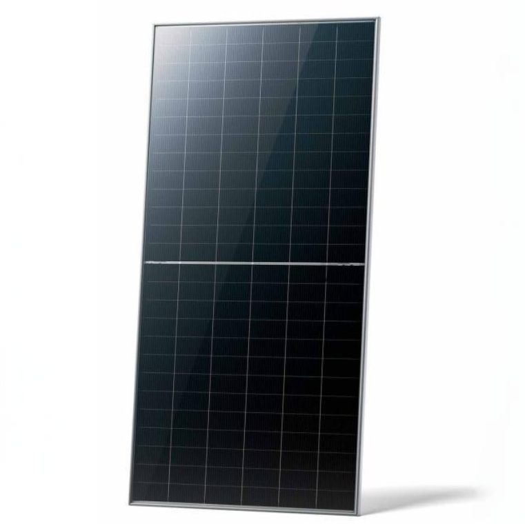
Mechanical Characteristics

image.png

Packaging Configuration

image.png

Specifications (STC)

image.png

Application Conditions

image.png


Engineering Drawings

image.png

*Note: For specific dimensions and tolerance ranges, please refer to the corresponding detailed module drawings.

Electrical Performance 


image.png

image.png

What is TOPCon technology?

TOPCon technology (Tunnel Oxide Passivated Contact) is an advanced photovoltaic cell technology used to enhance the efficiency of solar cells in converting sunlight into electricity. The essence of TOPCon technology is the introduction of a tunneling oxide layer and a doped polysilicon layer on the rear side of the cell, which forms a passivated contact structure. This structure reduces surface recombination and metal contact recombination, thereby improving the performance of the cell.

  • Tunnel Oxide Layer: An ultra-thin tunneling oxide layer is fabricated on the back side of the cell. This layer is thin enough to allow electrons to tunnel through but thick enough to reduce surface recombination losses.

  • Doped Polysilicon Layer: A layer of doped polysilicon is deposited on top of the tunneling oxide layer. This layer can be either N-type or P-type doped and is used to collect charge carriers.

  • Passivated Contact: The passivated contact structure, formed by the tunneling oxide layer and the doped polysilicon layer, effectively reduces surface recombination and metal contact recombination, thereby increasing the cell's open-circuit voltage and short-circuit current.


Know your supplier
Wone
Main Categories
High voltage/Low voltage/Wire cable/Instrument meters/New energy/Tester/Production equipment/Generator/Electrical fittings/Integrated Electrical Equipment
Business Type
Design/Manufacture/Sales
Highest Annual Export (USD)
$50,000,000
Professional Experience
1 years
Workplace
65666m²m²
占位
占位
Related Products
Related Knowledges
The design of the three-purpose grounding transformer
Underground Power Cable Transmission LinesDirect - buried power cable lines have large ground - distributed capacitance, causing high single - phase - to - ground short - circuit capacitive current. For 10 kV lines, if this current exceeds 10 A, arcs hardly self - extinguish, risking arc overvoltage and endangering line equipment. Arc extinction is thus necessary. With a Dyn - connected main transformer, an arc - suppression coil on the secondary neutral point suffices. For Yd - connected ones,
Dyson
06/12/2025
Failure Analysis and Design Optimization of Conventional Grounding Transformers
I. Core Cause of Damage: Electrodynamic Impact (Complying with GB/T 1094.5 / IEC 60076-5)The direct cause of high-voltage winding end collapse is the instantaneous electrodynamic impact induced by short-circuit current. When a single-phase grounding fault occurs in the system (such as lightning overvoltage, insulation breakdown, etc.), the grounding transformer, as the fault current path, withstands high-amplitude and steep-rise-rate short-circuit currents. According to Ampère's force law
Felix Spark
06/12/2025
Analysis of Grounding Transformer Operational Behavior Under System Single-Phase-to-Ground Fault Conditions
1 Theoretical AnalysisIn distribution networks, grounding transformers serve two key roles: powering low - voltage loads and connecting arc - suppression coils at neutrals for grounding protection. Grounding faults, the most common distribution network fault, heavily impact transformers’ operating characteristics, causing sharp changes in electromagnetic parameters and status.To study transformers’ dynamic behaviors under single - phase grounding faults, build this model: Assume a tr
Felix Spark
06/12/2025
Design Calculations for Neutral Grounding Schemes and Grounding Transformer Sizing in Utility-Scale Solar PV Plants
1 Classification of Neutral Grounding Methods for Solar Photovoltaic Power StationsInfluenced by differences in voltage levels and grid structures across regions, the neutral grounding methods of power systems are mainly categorized into non-effective grounding and effective grounding. Non-effective grounding includes neutral grounding via arc suppression coils and neutral ungrounded systems, while effective grounding comprises neutral solid grounding and neutral grounding via resistors. The sel
Dyson
06/12/2025
Zero-Sequence Impedance Characterization of Dry-Type Grounding Transformer with ZN Connection
In a neutral-insulated three-phase power system, an earthing transformer provides an artificial neutral point, which can be solidly earthed or earthed via reactors/arc suppression coils. The ZNyn11 connection is typical, where zero-sequence magnetomotive forces in the inner/outer half-windings of the same core column cancel out, balancing fault currents in series windings and minimizing zero-sequence leakage flux/impedance.Zero-sequence impedance is critical: it determines fault current magnitud
Dyson
06/12/2025
Case Analysis on Maloperation of Grounding Transformer Overcurrent Protection Relay
The neutral grounding mode refers to the connection between the power system neutral point and ground. In China's 35 kV and below systems, common methods include ungrounded neutral, arc-suppression coil grounding, and small-resistance grounding. The ungrounded mode is widely used as it allows short-term operation during single-phase grounding faults, while small-resistance grounding has become mainstream for its fast fault removal and overvoltage limitation. Many substations install grounding tr
Felix Spark
06/12/2025
×
Inquiry
Download
Experts Electrical is dedicated to serving the personnel in the global power industry.
Join Experts Electrical, not only can you discover power equipment and power knowledge, but also canhnd like - minded friends!
商品视频播放