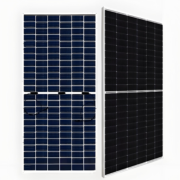
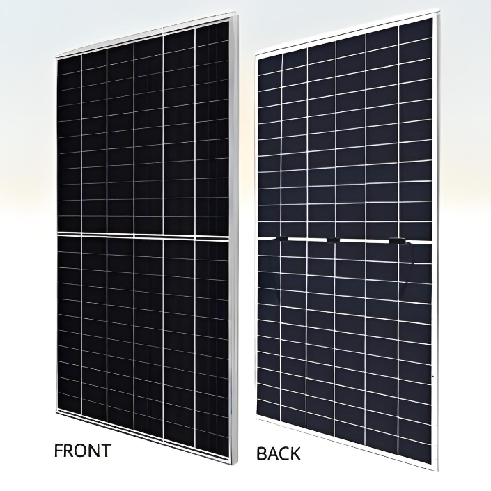
530 W - 555 W Bificial High Power Dual cell PERC Module(Mono)
discuss personally
Model
| Brand | POWERTECH |
| Model NO. | 530 W - 555 W Bificial High Power Dual cell PERC Module(Mono) |
| Power Bifaciality | 70% |
| Max. System Voltage | 1500V (IEC) |
| Max. Series Fuse Rating | 30A |
| Module Fire Performance | CLASS C |
| Max. power of the module | 555W |
| Max. efficiency of Module | 21.5% |
| Series | Bificial MONO PERC |
Features
Module power up to 555 W Module efficiency up to 21.5 %.
Up to 12.3 % lower LCOE Up to 5.2 % lower system cost.
Comprehensive LID / LeTID mitigation technology, up to 50% lower degradation.
Compatible with mainstream trackers, cost effective product for utility power plant.
Better shading tolerance.
Standard
Minimizes micro-crack impact.
Heavy snow load up to 5400 Pa, wind load up to 2400 Pa*.
Engineering drawing(mm)

CS6W-530MB-AG / I-V gurves

Electrical date/STC*

Electrical date/NMOT*

Electrical date

Mechanical charactheristics

Temperature characteristics

How does PERC work?
Definition:
PERC technology is a design improvement technology for photovoltaic cells, aiming to enhance the overall photoelectric conversion efficiency of the cells by reducing recombination losses on the back surface and improving back surface reflection.
Working Principle:
Passivation: By adding a dielectric passivation layer (such as aluminum oxide Al2O3 or silicon nitride SiN) on the back of the cell, the recombination losses on the back surface are reduced, that is, the non-radiative recombination of photogenerated carriers on the back surface is decreased.
Reflection: The passivation layer also has a high reflectivity, which can reflect the unabsorbed light back into the cell, increasing the absorption probability of photons and thereby enhancing the short-circuit current (Is).
Hole-opening: Holes are opened on the passivation layer (by means of lasers, etc.) to form metal contact points for current collection.