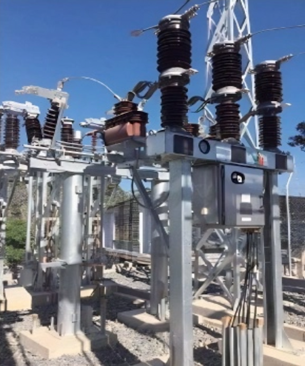
40.5kV HV Gas circuit breaker
discuss personally
Model
| Brand | Wone |
| Model NO. | 40.5kV HV Gas circuit breaker |
| Rated voltage | 40.5kV |
| Rated normal current | 2500A |
| Rated frequency | 50/60Hz |
| Rated short circuit breaking current | 31.5kA |
| Series | LW36-40.5 |
Product introduction
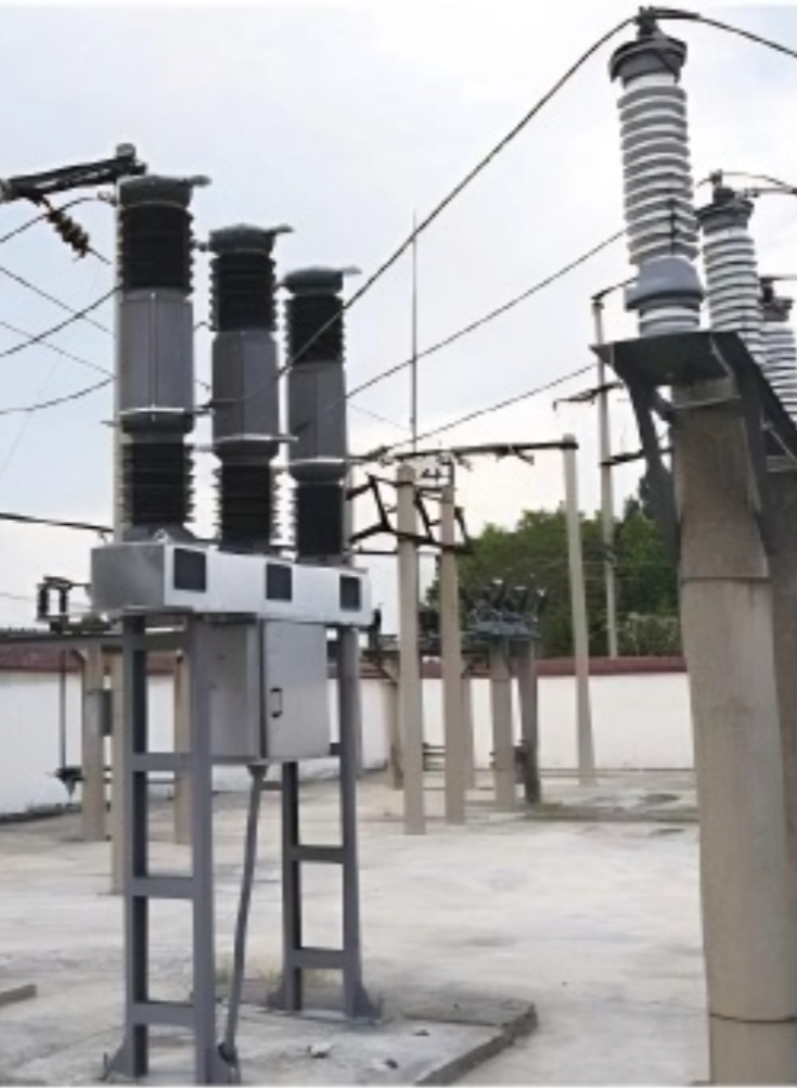
LW36-40.5 outdoor self-energy HV AC SF6 circuit breaker is an outdoor three-phase HV AC equipment used in electricity grids with altitudes of no more than 3000m, environment temperatures of no less than -40℃, local pollution classes of no higher than Class IV, and AC 50Hz/60Hz with maximum voltage of 40.5kV, it is suitable for the control and protection of HV supply and transformation lines in power station, converting stations, and industrial and mining enterprises. it can also be used as connection circuit breaker.
Main characteristic
LW36-40.5 self-energy HV SF6 circuit breaker is equipped with advanced hot-expansion plus auxiliary pressure gas self-energy arc extinguishing technology and matched with new-type spring actuating mechanism, it has features such as long electrical endurance, small operating power, high electrical and mechanical reliability, high technical parameters, and moderate price. Lt’s main performance features are as follows:
1、High rated technical parameters: rated current 2500A/4000A and rated short circuit breaking current 31.5KA/40KA/50KA.suitable for the opening and closing of large-capacity electricity grids.
2、High electrical reliability
No-load line charging breaking ability and no-load cable charging breaking ability 50/60Hz dual-frequency C2,back-to-back capacitor bank breaking ability 50/60Hz dual-frequency C2, no re-breakdown;
Strong external insulation ability;, suitable for regions with 3000m of altitude or Class lV pollution.
3、High reliability of operating mechanism:
Mechanical endurance: separating and closing for 10000 times without replacing parts; can meet the user' s requirement of continuous running and little maintenance.
New type spring actuating mechanism has few components parts; overall high-strength cast aluminum frame and brake separating and closing spring; and centralized arrangement is adopted for the buffer, compact structure, reliable operation, low noise, and convenient maintenance; suitable for frequent operations.
4、Al exposed parts are made of stainless steel materials or hot-galvanized on the surface for high corrosion resistance.
5、Reliable sealing structure ensures the product annual leakage rates≤0.5%.
6、Four internally attached current mutual inductors for every phase can be installed on the circuit breaker. Microcrystal alloy and high permeability material are adopted for internally attached current mutual inductors. The accuracy of 200A and above current mutual inductors can reach up to Level 0.2 or 0.2S. Reliable electrical screening design is adopted for the cable coils of internally attached current mutual inductors to improve the electric field distribution of the mutual inductors and promote the internal insulation of the product. it can withstand 120kv and 5min working frequency withstand voltage test and the internal insulation is not interfered by the short circuit breaking working conditions, which makes it safe and reliable.
Main technical parameters

Order notice
Model and format of the circuit breaker.
Rated electrical parameters (voltage, current, breaking current, etc.);
Environmental conditions for using (environment temperature, altitude, and environment pollution level);
Rated control circuit electrical parameters (power-storage electromotor rated volage and brake separating and closing cable coil rated voltage);
Names and quantities of spare items needed, parts and special equipment and tools (to be otherwise ordered);
The wire connecting direction of the primary upper terminal.