| Brand | Wone |
| Model NO. | Shunt Reactor |
| Rated voltage | 35kV |
| Rated normal current | 5000A |
| Series | BKDGKL |
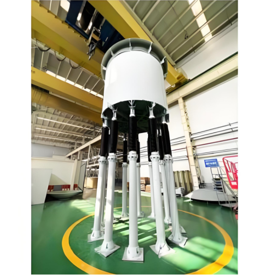
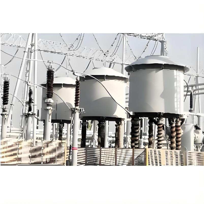
Description:
The shunt reactor is connected between the phase and the ground, between the phase and the neutral point , between phases in the power system to play the role of reactive power compensation. It is used to compensate the capacitive charging power of ultra-high voltage lines, which is helpful to limit the increase of power frequency voltage and operating over-voltage in the system, reduce the insulation level of ultrahigh voltage system, improve the voltage distribution along the line and increase the stability and power transmission capacity of the system.
Electrical schematic:

Reactor Code and Designation:

Parameters:

What is the reactive power compensation principle of shunt reactor?
Reactive Power Compensation Principle:
In power systems, most loads are inductive (such as motors, transformers, etc.). Inductive loads consume reactive power during operation, which can lead to a decrease in the power factor of the grid.
When a shunt reactor is connected to the grid, its primary function is to provide inductive reactive power to the grid. According to the principle of electromagnetic induction, when an alternating current flows through the windings of the reactor, it generates an alternating magnetic field in the core. This magnetic field interacts with the electric field in the grid, facilitating the exchange of reactive power.
When the grid lacks reactive power, the shunt reactor absorbs capacitive reactive power (equivalent to generating inductive reactive power), thereby increasing the power factor of the grid. This reduces the transmission of reactive currents in the grid, lowers line losses, and improves the efficiency and quality of power transmission.
Example:
In the distribution network of an industrial enterprise, if a large number of asynchronous motors are operating simultaneously, the power factor of the grid can drop to a low level. Installing a shunt reactor in this scenario can compensate for the reactive power, raising the power factor to a reasonable range. This not only reduces the company's electricity costs but also alleviates the burden on the grid.