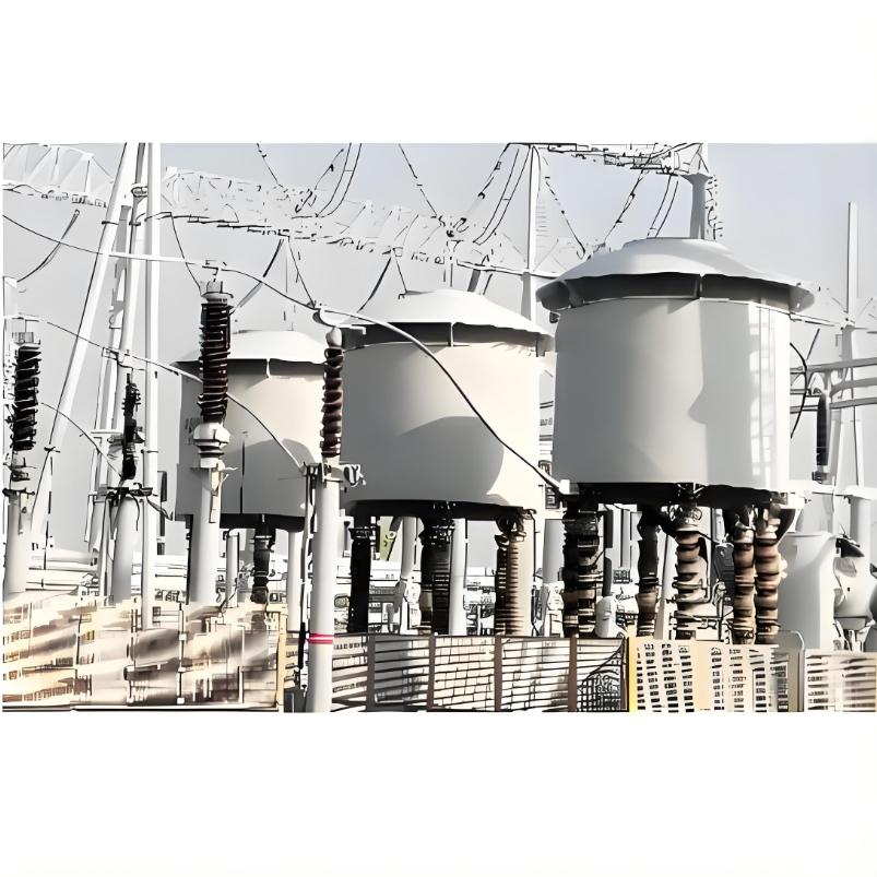
10kV 35kV 500kV The system line Current-Limiting Reactor of connected
discuss personally
Model
| Brand | Wone |
| Model NO. | Current-Limiting Reactor |
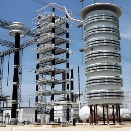
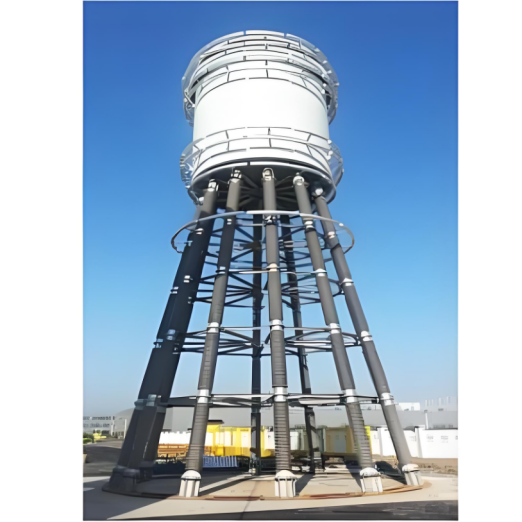
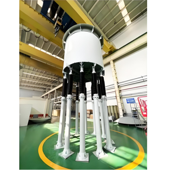
| Rated voltage | 500KV |
| Rated normal current | 4000A |
| Series | XKDGKL |
Up to 500kV
Description:
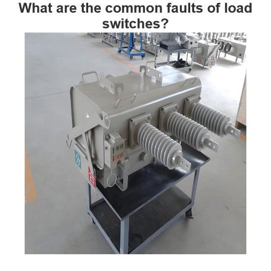
The current-limiting reactor is connected in series in the system line to limit the short-circuit current or fault current of the system to a specified value when a system fault occurs.
Electrical schematic:

Reactor Code and Designation:

Parameters:
XK Current Limiting Reactor Series Table

High Voltage Current Limiting Reactor Series Table

What is the principle of action of the current-limiting reactor on the transient current and the steady-state current?
Effects on Transient and Steady-State Currents:
Transient Currents:
During transient processes in power systems, such as those caused by switching operations or lightning strikes, which result in sudden changes in current, a series-connected air-core current-limiting reactor can effectively suppress the peak values of transient currents. This reduces the impact of these transient events on the equipment.
Steady-State Currents:
During steady-state operation, the reactor can also appropriately limit the normal operating current according to the system's design requirements, ensuring that the current in the circuit remains within safe limits.
Example:
In the power supply systems of large industrial enterprises, when starting large inductive loads such as motors, significant starting currents can be generated. A series-connected air-core current-limiting reactor can limit the magnitude of these starting currents, preventing adverse effects on the grid and other equipment. This ensures that the motor can start smoothly without causing disruptions to the power system.