1 Introduction
With the national economy’s steady growth, electricity demand surges. For rural grids, rising loads, uneven power - supply distribution, and limited main - grid voltage regulation leave some 10 kV long lines (exceeding national radius standards) in remote/weak - grid areas. These lines face poor voltage quality, low power factor, and high losses. Due to cost and investment constraints, mass high - voltage nodes or grid expansion aren’t feasible. The 10 kV feeder automatic voltage regulator offers a technical fix for long - radius, low - voltage issues.
2 Working Principle of the Voltage Regulator
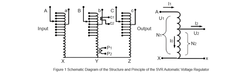
The SVR automatic regulator has a main circuit (three - phase autotransformer + on - load tap - changer, structure in Figure 1) and a control unit. Its core has shunt, series, and control voltage coils:
- Series coil: Multi - tapped, connected between input/output via the tap - changer, adjusts output voltage.
- Shunt coil: Common winding, generates energy - transfer magnetic fields.
- Control voltage coil: Wound on the shunt coil, powers the controller/motor and provides measurement voltage.
Working logic: Tap positions on the series coil (via the on - load tap - changer) alter input - output turns ratios, adjusting output voltage. On - load switches typically have 7 or 9 gears (user - selectable per needs). The regulator’s primary - secondary turns ratio matches transformers, i.e.:

3 Application Example
3.1 Line Status
A 10 kV line has a main trunk length of 15.138 km, using two conductor models: LGJ - 70mm² and LGJ - 50mm². The total capacity of distribution transformers is 7260 kVA. During peak load periods, the voltage on the 220V side of distribution transformers in the middle and rear sections of the line drops to as low as 175V.
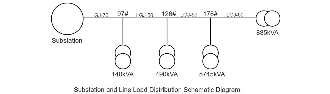
For the LGJ - 70 line, the resistance per kilometer is 0.458 Ω and the reactance per kilometer is 0.363 Ω. Then, the line resistance and reactance from the substation to pole 97# of the main trunk line are respectively:
R = 0.458 × 6.437 = 2.95Ω
X = 0.363 × 6.437 = 2.34Ω
According to the distribution transformer capacity and load rate of the line, the voltage loss from the substation to pole 97# of the main trunk line can be calculated as:

- Δu — Line voltage drop, unit: kV.
- R — Line resistance, unit: Ω.
- X — Line reactance, unit: Ω.
- r — Resistance per unit length, unit:Ω.
- x — Reactance per unit length, unit: Ω.
- P — Active power of the line, unit: kW.
- Q — Reactive power of the line, unit: kvar.
Then, the voltage at pole 97# of the main trunk line is only: 10.4 - 0.77 = 9.63 kV at pole 178 can be calculated as: 8.42 kV.The voltage at the end of the line is: 8.39 kV.
3.2 Solutions
To ensure voltage quality, the main voltage regulation methods and measures in medium - and low - voltage distribution networks include the following aspects:
- Build a new 35 kV substation to shorten the power supply radius of 10 kV lines.
- Replace the conductor cross - section to reduce the line load rate.
- Install reactive power compensation for the line. This method has a poor regulation effect for situations with long lines and large loads.
- Install an SVR feeder automatic voltage regulator. It has a high degree of automation, good voltage regulation effect, and flexible use. Below, three methods are used to compare schemes for improving the voltage quality at the end of the 10 kV block line.
3.2.1 Scheme of Building a New 35 kV Substation
Expected Effect Analysis: Building a new substation can shorten the power supply radius, improve the terminal voltage of longer lines, and enhance power supply quality. This scheme can solve the voltage problem well, but the investment is relatively large.
3.2.2 Scheme of Reconstructing the 10 kV Main Trunk Line
Changing line parameters mainly involves increasing the conductor cross - sectional area. For lines with relatively scattered users and small conductor cross - sectional areas, the resistance component in voltage loss accounts for a relatively large proportion. Therefore, reducing the conductor resistance can achieve a certain voltage regulation effect. The 10 kV terminal voltage can be adjusted from 8.39 kV to 9.5 kV.
3.2.3 Scheme of Installing an SVR Feeder Automatic Voltage Regulator
Install 1 set of 10 kV automatic voltage regulators to solve the problem of low voltage at the terminal of the line after pole 161.
Expected Effect Analysis: The 10 kV terminal voltage can be adjusted from 8.39 kV to 10.3 kV.
After comparative analysis, the third solution is the most economical and practical. The SVR feeder automatic voltage regulation complete set device achieves the stability of the output voltage by adjusting the turns ratio of the three - phase autotransformer and has the following major advantages:
- It can realize fully automatic and on - load voltage regulation. The transformer itself adopts a star - connected three - phase autotransformer, which has a large capacity and a small volume and can be erected between two poles (S ≤ 2000 KVA).
- The voltage regulation range is generally - 10% ~ + 20%, which can meet the voltage requirements.
According to theoretical calculations, it is recommended to install an SVR feeder automatic voltage regulator with the model SVR - 5000/10 - 7 (0 ~ + 20%) on the main trunk line. After installing the voltage regulator, the maximum voltage of pole 141 can be adjusted to:
U161=U×10/8=10.5 kV
In the formula:
- U161 — The voltage at the installation point after the voltage regulator is installed.
- 10/8 — The maximum turns ratio of the voltage regulator with a voltage regulation range of 0 ~ + 20%.
Actual operation has proven that the function and performance of the SVR feeder automatic voltage regulation complete set device, which automatically tracks changes in the input voltage to ensure a constant output voltage, are very stable, and it is effective in low - voltage governance.
3.2.4 Benefit Analysis
Using the SVR voltage regulator on the line saves a large amount of funds compared to building a new substation or replacing conductors. Not only is the line voltage increased to meet relevant national regulations, resulting in good social benefits; when the line load remains unchanged, increasing the line voltage reduces the line current, to a certain extent reducing line losses, achieving the goal of loss reduction and energy conservation, and improving the economic benefits of the enterprise.
4 Conclusion
For areas with limited load growth potential, especially rural power grids featuring 10 kV long lines—where power supply points are insufficient, supply radii are large, line losses are high, loads are overburdened, and no nearby 35 kV substation power supply is available in the short to medium term—the SVR feeder automatic voltage regulator offers a solution. It addresses low voltage quality and high electrical energy losses without the need to build or delay constructing 35 kV substations.
This approach delivers significant social and economic benefits. Additionally, with an investment cost roughly one - tenth of building a new 35 kV substation, the SVR is highly worthy of promotion in rural power grid applications.