Application Analysis of Load Switch and Current-Limiting Fuse Combination Apparatus
Echo
06/27/2025
As an expert in the application and trends of electrical equipment, I have a profound mastery of knowledge in circuits, power electronics, etc. I possess a comprehensive set of abilities including equipment design, fault diagnosis, and project management. I can precisely grasp the industry's pulse and lead the development of the electrical field.
Method for Automatic Isolation of Customer Equipment Faults by Load Switches in Distribution Networks
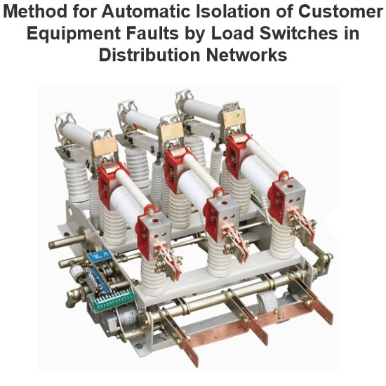
1 OverviewDistribution network safety has long been under - addressed, with its automation lagging substation automation . Using 10 kV intervals of existing substations to set line section points meets future grid needs . Configuration of distribution switches, section switches, and protection must match substation outgoing - line protection for reliability. Fault isolation, self - healing, and restoration are key to distribution automation .Scholars have studied smart distribution network fault
Felix Spark
06/30/2025
A Novel Detection Method for Stuck Faults in Load Switches
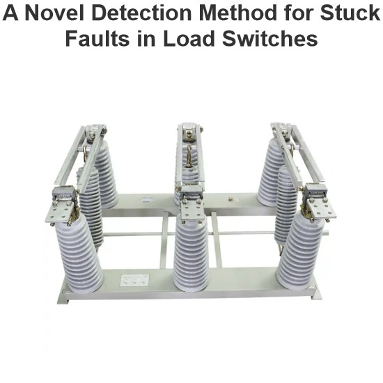
In recent years, as distribution automation advances, load switches see wider use in distribution lines. Yet, mechanical - failure - induced accidents are on the rise, burdening line operation and maintenance.Poor mechanical performance is the main cause of switch faults. Many scholars study large - scale switchgear operation, using methods like coil current detection, vibration signal analysis, switch travel testing, ultrasonic flaw detection, and infrared thermometry. Motor - current - based s
Oliver Watts
06/30/2025
What tests need to be conducted for load switches?
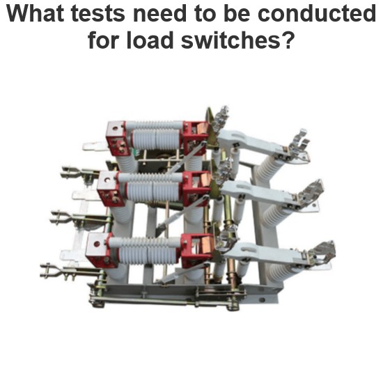
As a technician with years of on-site experience in power testing, I understand the importance and complexity of load switch testing. Below, I combine practical work experience to elaborate on the full process of load switch testing, from testing items and methods to equipment and procedural specifications.I. Routine Electrical Performance Testing(1) Loop Resistance TestLoop resistance is a core indicator for evaluating a load switch's conductivity. I strictly follow GB/T 3804 and GB 1984 standa
Oliver Watts
06/28/2025
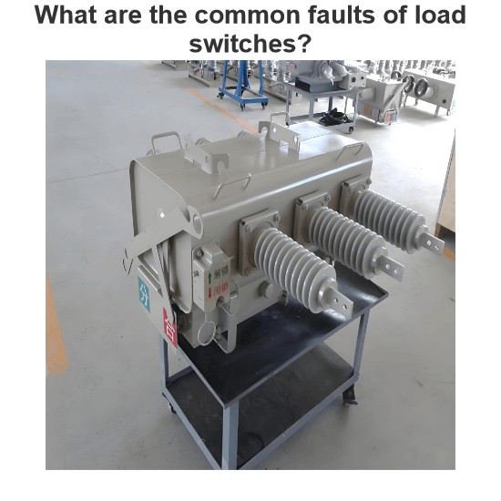
What are the common faults of load switches?
As an on-site maintenance technician, I frequently deal with electrical, mechanical, and insulation faults in load switches. The following outlines fault manifestations, causes, and solutions:I. Electrical Fault Handling(1) Contact HeatingContact heating is mainly caused by poor contact, insufficient pressure, or three-phase asynchrony. When the contact resistance exceeds 1.5 times the initial value, the temperature rise will exceed the standard in a 40℃ environment. For example, the FW4-10 swit
Felix Spark
06/28/2025
