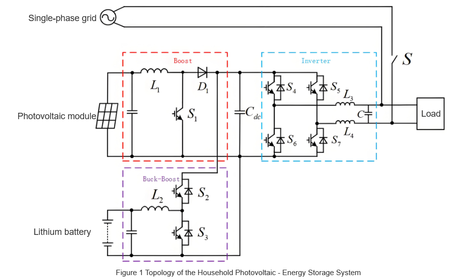
2 Analysis of System Operation Modes and Energy Flow
Guided by the energy management algorithm, the system’s operation splits into independent and grid - connected modes, each further subdivided as follows:
2.1 Independent Operation (By Main Power)
Two sub - modes exist, defined by the power source controlling the DC bus:
-
PV - Driven Mode
- Trigger: PV output > load, battery not full.
- Logic:
- PV as main power; Boost runs in CV mode to stabilize DC bus.
- Inverter works in independent inversion for load supply.
- If PV power > load + battery charge power, Buck - Boost uses Buck mode to charge the battery; else, Buck - Boost idles.
-
Battery - Driven Mode
- Trigger: PV output < load, battery has remaining capacity.
- Logic:
- Battery as main power; Buck - Boost runs in Boost mode to stabilize DC bus.
- Inverter uses independent inversion for load supply.
- If PV has weak output, Boost operates in MPPT mode; if no PV output, Boost idles.
2. 2 Grid - Connected Operation (By Inverter State)
Split by whether the inverter is in inversion or rectification:
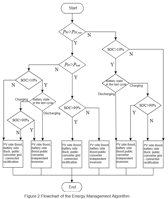
2.3 Mode Boundaries & Coordination
The 4 sub - modes’ trigger conditions and equipment coordination are detailed in Table 1 (to be added). Through dynamic switching of “PV - battery - grid” power and adaptive control of Boost/Buck - Boost converters and the inverter, the system enables efficient energy flow in “generation - storage - consumption”, covering all household power needs (off - grid, grid - connected, emergency, etc.).
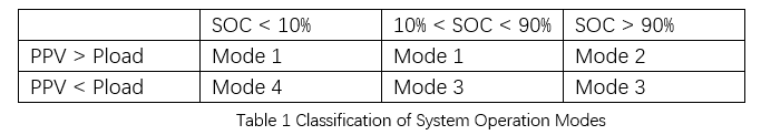
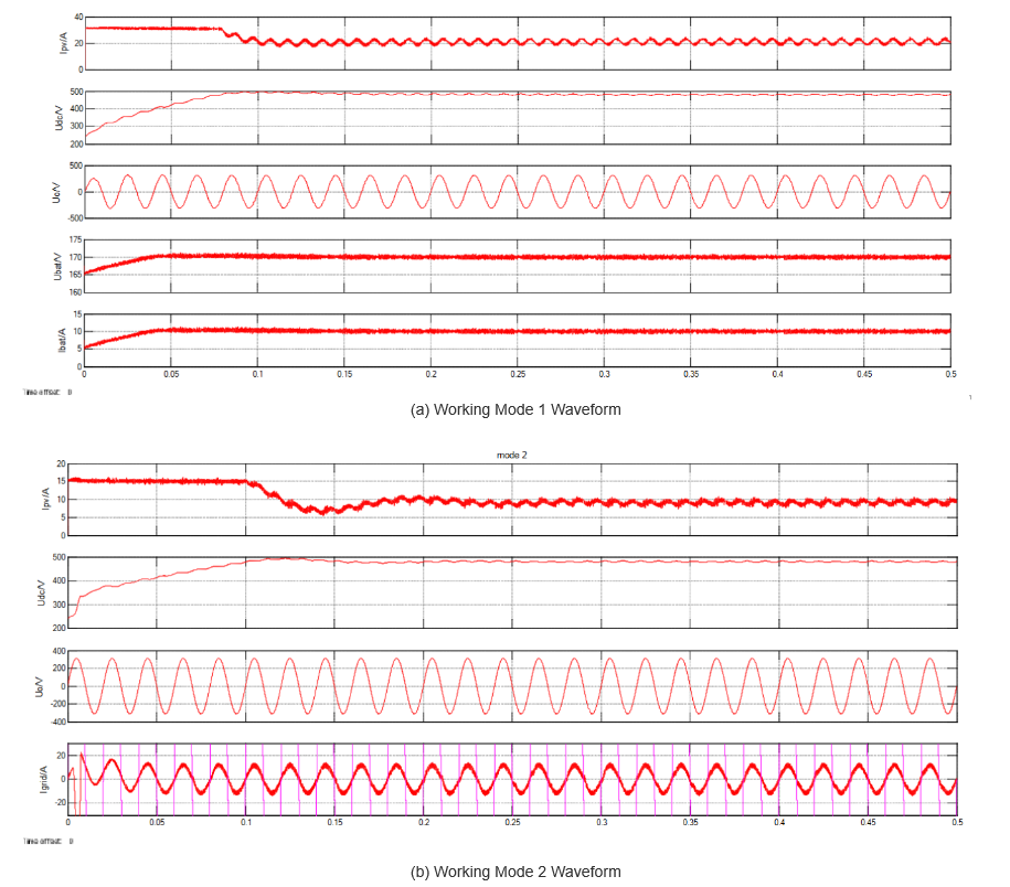
Figure 3(a) shows the waveform for Mode 1: PV output = 4.8 kW, load = 3 kW. The PV module outputs 240 Vdc; the Boost converter stabilizes the DC bus at 480 Vdc. The inverter runs in independent inversion (220 Vac for loads), and the Buck - Boost works in Buck mode (1.8 kW to charge the battery). Waveforms (top to bottom): PV output current, DC bus voltage, inverter output voltage, and battery charging current.
Figure 3(b) corresponds to Mode 2: PV output = 5 kW (battery full, so Buck - Boost is off). Load = 3 kW; the inverter uses grid - connected inversion to keep the DC bus at 480 Vdc, feeding excess energy to the grid (9 A, synchronized with grid voltage). Waveforms: PV output current, DC bus voltage, inverter output voltage, and grid - connected current.
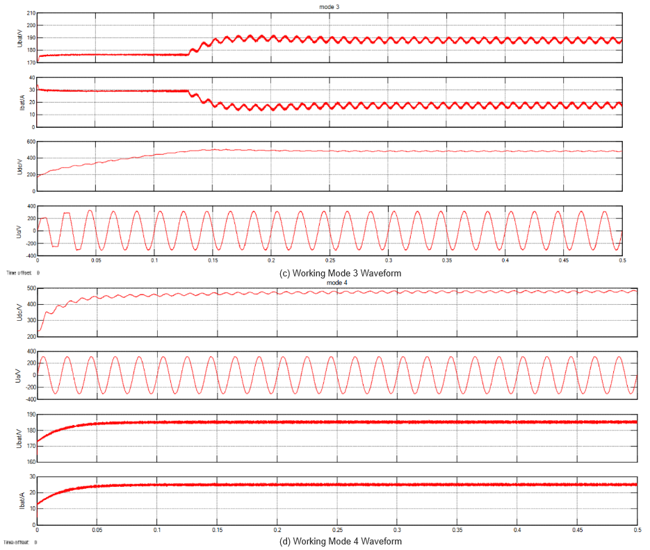
Figure 3(c) shows Mode 3: The PV module hits limits (no output, Boost off). The energy storage unit powers the system; the Buck - Boost runs in Boost mode (DC bus = 480 Vdc). The inverter uses independent inversion (220 Vac for 3 - kW loads). Waveforms: Battery discharge current, DC bus voltage, and inverter output voltage.Figure 3(d) presents Mode 4: Both PV and energy storage hit limits (no output). The grid powers loads (3 kW) and charges the battery; the inverter uses grid - connected rectification (DC bus = 480 Vdc).
3. Conclusion (Street - lamp Maintenance)
Current urban street - lamp maintenance has shortcomings. To improve, focus on four areas:
- Broaden funding for sufficient maintenance budgets.
- Strengthen publicity/inspections to resolve issues timely.
- Promote green lighting to cut costs and boost efficiency.
- Establish standardized management systems for uniform operations.
These steps will enhance street - lamp management efficiency, supporting smart city operations and green development.