For long-distance electrical power transmission, the voltage and current levels are extremely high, making direct measurement with conventional meters impossible. Instrument transformers, including current transformers (CTs) and potential transformers (PTs), are used to step down these levels to safe magnitudes, enabling measurement with standard meters.
What is a Transformer?
A transformer is an electrical device that transfers energy between circuits via mutual induction. It consists of two magnetically coupled yet electrically isolated coils—primary and secondary—designed to adjust voltage and current levels without altering frequency. Transformers serve diverse applications, including power transformers, autotransformers, isolation transformers, and instrument transformers. Among these, current transformers and potential transformers are specialized instrument transformers for measuring high currents and voltages in power lines.
Current Transformer (CT)
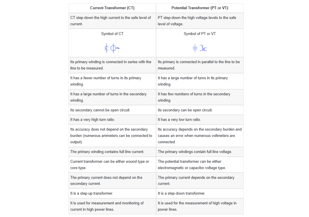
A current transformer (CT) is an instrument transformer that reduces high currents to low levels, allowing measurement with a standard ammeter. It is specifically designed for quantifying high-current flows in power transmission lines.

A current transformer (CT) is a step-up transformer that reduces primary current while increasing secondary voltage, stepping down high currents to just a few amperes—levels measurable by standard ammeters. Crucially, its secondary voltage can become extremely high, necessitating a strict operational rule: the CT secondary must never be left open-circuited while primary current is flowing. CTs are connected in series with the power line carrying the current to be measured.
Potential Transformer (PT/VT)
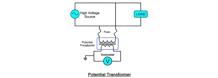
A potential transformer (PT, also called a voltage transformer or VT) is an instrument transformer designed to reduce high voltages to safe, measurable levels for standard voltmeters. As a step-down transformer, it converts high voltages (ranging up to hundreds of kilovolts) to low voltages (typically 100–220 V), which can be directly read by conventional voltmeters. Unlike CTs, PTs feature low secondary voltages, allowing their secondary terminals to be safely left open-circuited without risk. PTs are connected in parallel with the power line carrying the voltage to be measured.
Beyond voltage reduction, a potential transformer (PT) provides electrical isolation between high-voltage power lines and low-voltage measurement circuits, enhancing safety and preventing interference in the metering system.
Types of Potential Transformers
There are two primary configurations:
Comparison between Current Transformer and Voltage or Potential Transformer