In an electrical power system, various devices are utilized to enhance power factor and operational efficiency. Shunt capacitors and shunt reactors represent two distinct components designed to optimize the performance of electrical grids. This article explores their key differences, beginning with an overview of their fundamental principles.
Shunt Capacitors
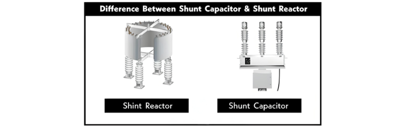
A shunt capacitor refers to a single capacitor or a group of capacitors (termed a capacitor bank) connected in parallel to the power system. It serves to improve the power factor and operational efficiency of the system by compensating for inductive loads, thereby enhancing the system's power factor.
Most loads in an electrical power system—such as electric machines, transformers, and relays—exhibit inductive characteristics, contributing inductive reactance alongside the inductance of power lines. Inductance causes current to lag behind voltage, increasing the lagging angle and decreasing the system's power factor. This lagging power factor leads the load to draw more current from the source for the same power rating, resulting in additional line losses as heat.
The capacitance of a capacitor causes current to lead voltage, allowing it to cancel out inductive reactance in the power system. Multiple capacitor units (a capacitor bank) connected in parallel to improve the power factor are known as shunt capacitors.
Shunt Reactors
A shunt reactor is a device used in power systems to stabilize voltage during load variations, thereby enhancing efficiency. It compensates for capacitive reactive power in power transmission lines, typically applied in 400kV or higher voltage transmission lines.
Constructed with a single winding—either directly connected to the power line or the tertiary winding of a three-phase transformer—it absorbs reactive power from the lines to improve system efficiency.
Differences Between Shunt Capacitors and Shunt Reactors
The following table outlines the key comparisons between shunt reactors and shunt capacitors:
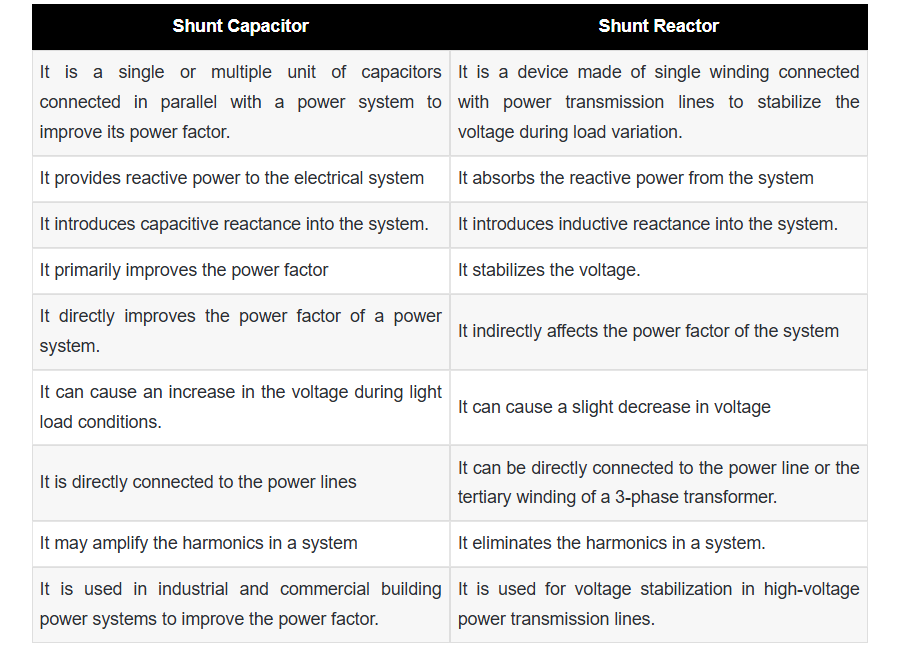
Comparison Between Shunt Capacitors and Shunt Reactors
Function
- Shunt Capacitor: Supplies reactive power to the electrical system, absorbed by inductive loads (e.g., motors, transformers) to improve power factor and system efficiency.
- Shunt Reactor: Absorbs and controls reactive power flow to enhance efficiency, stabilize voltage levels, and mitigate voltage surges/transients in the grid.
Power Factor Correction
- Shunt Capacitor: Directly improves power factor by providing reactive power compensation.
- Shunt Reactor: Indirectly improves power factor by stabilizing voltage in transmission lines.
Connection
- Shunt Capacitor: Connected directly in parallel with the power line.
- Shunt Reactor: Connected either directly to the power line or via the tertiary winding of a three-phase transformer.
Voltage Impact
- Shunt Capacitor: May cause voltage rise during light-load conditions due to reactive power injection.
- Shunt Reactor: Induces slight voltage drop due to inductive reactance, balancing excessive reactive power.
Harmonics Effect
- Shunt Capacitor: Prone to creating resonant conditions that amplify voltage harmonics.
- Shunt Reactor: Dampens and suppresses harmonics, improving power quality.
Applications
- Shunt Capacitor: Widely used in industrial and commercial power systems to correct power factor in distribution networks.
- Shunt Reactor: Primarily applied in high-voltage (400kV+) transmission lines for voltage stabilization and transient suppression.
Conclusion
Both shunt capacitors and shunt reactors optimize electrical power system efficiency, though via distinct mechanisms: capacitors enhance power factor by compensating inductive loads, while reactors stabilize voltage and mitigate harmonics in transmission networks. Their complementary roles ensure reliable power delivery across diverse operational scenarios.