Common Faults and Treatment Methods of 10kV Vacuum Circuit Breakers
Overview
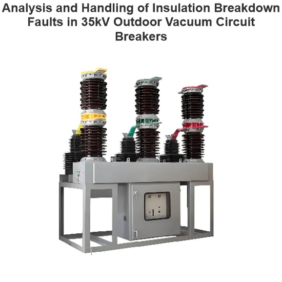
The 10kV vacuum circuit breaker takes advantage of the property of using vacuum as the insulation and arc - extinguishing medium between contacts, which makes it widely applied in substations and distribution networks. However, the number of faults occurring during its specific application has been on the rise. This article classifies and analyzes the common faults in its operation, discusses different types of fault treatment methods, and presents routine maintenance measures.
Fault Phenomena and Treatment Methods of the Vacuum Circuit Breaker Itself
The low vacuum degree in the vacuum interrupter is the most prone - to - occur fault of the 10kV vacuum circuit breaker. The vacuum circuit breaker interrupts current and extinguishes arcs inside the vacuum interrupter. Generally, the vacuum circuit breaker is not equipped with equipment or devices for qualitatively and quantitatively measuring the vacuum - degree characteristics.
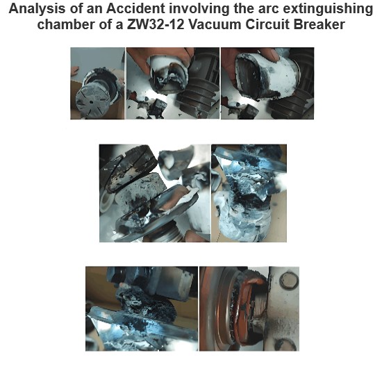
Therefore, the fault of low vacuum degree is usually quite hidden, and it is difficult to detect during maintenance and operational testing. Its hazard level is far greater than that of other obvious faults. When the vacuum degree drops to the point where the circuit breaker can no longer extinguish arcs normally, it may even lead to serious consequences such as the burning or explosion of the breaking point.
Reasons for the Low Vacuum Degree in the Vacuum Interrupter
-
There are problems with the material of the vacuum interrupter, causing the vacuum interrupter to leak gas, or the manufacturing process is not refined, resulting in the existence of leakage points in the vacuum interrupter itself, thus affecting its vacuum degree.
-
After long - time operation, when the circuit breaker performs a certain action, the generated vibration may also cause the sealing part of the vacuum interrupter to become loose, thereby reducing the vacuum degree of the vacuum interrupter. Especially for vacuum circuit breakers equipped with CD10 mechanisms, when the circuit breaker performs the opening and closing operations of the current, it is easy to generate a large impact on the sealing connection part of the vacuum interrupter, resulting in poor sealing and a decrease in the vacuum degree.
-
There are problems with the material or manufacturing of the bellows in the vacuum interrupter, and leakage points appear after multiple operations.
-
The vacuum interrupter is accidentally damaged during routine maintenance work.
Treatment Methods for the Low Vacuum Degree in the Vacuum Interrupter
Preventive tests should be carried out, and the vacuum degree of the vacuum interrupter should be regularly checked. During daily equipment inspection and maintenance, AC withstand voltage tests (between breaking points) should be frequently conducted. When conditions permit, a vacuum tester can be used to conduct a qualitative test on the vacuum degree of the vacuum interrupter to ensure that the vacuum degree of the vacuum interrupter is maintained at a certain level to meet the operational requirements of the circuit breaker.
When selecting and installing a vacuum circuit breaker, it is necessary to choose the mature products of manufacturers with good reputation and quality, and its supporting mechanism should preferably be one that has a relatively small impact on the circuit breaker. When patrolling equipment, maintenance personnel should pay attention to observing whether the metal shield of the vacuum interrupter has changed color or made abnormal sounds during operation.
For existing circuit breakers with severe pollution, timely cleaning and maintenance of the equipment should be carried out to prevent dust or other contaminants from affecting the insulation performance of the circuit breaker. If it is determined through inspection that the vacuum interrupter has defects, the vacuum interrupter should be replaced in a timely manner.
Fault Phenomena and Treatment Methods of the Control Circuit
The fuses in the signal circuit blowing and the opening and closing coils burning out are among the common faults in the operating circuit. The symptom is that the circuit breaker cannot operate electrically when in the opening or closing state, and the indicator light does not turn on. At this time, the microcomputer generally sends out a signal of "control circuit open - circuit". Such defects are relatively easy to detect and handle. One can directly check whether the opening and closing coils are burnt out and the magnitude of the resistance deviation. Replacing the problematic coil can eliminate the fault in the operating circuit.
The auxiliary contacts of the energy - storage travel switch (CK) are not connected, mainly due to the travel switch not being adjusted in place or being damaged, preventing the mechanism from being fully energy - stored. In this case, the energy - storage lamp (usually yellow) does not light up. The fault can be resolved by readjusting the position of the travel switch or replacing the travel switch to ensure the mechanism is fully energy - stored.
Ensuring the quality of the travel switch and improving its installation reliability are among the main ways to reduce the occurrence of circuit faults. In practical operation experience, the defects of the energy - storage travel switch of the CT19 mechanism are relatively obvious. During the closing process of a 10kV circuit breaker, the air switch of the control power supply tripped, ultimately leading to a control circuit open - circuit.
At this time, the line's tripping protection action occurred, and the faulty line experiencedoverride trip,expanding the power - outage range and causing serious impacts. Inspection revealed that when the travel switch fails to operate, the current loop cannot be effectively turned off, making it easy for the travel switch to arc when it acts, resulting in a large loop current that causes tripping. By replacing it with equipment of other models, this type of circuit fault can be effectively avoided.
The auxiliary switch (contacts) of the circuit breaker is damaged or not adjusted in place, causing the circuit to be unconnected or have poor contact. This generally manifests as a control circuit open - circuit, and the opening and closing indicator lights do not light up or flicker. When this situation occurs, it is necessary to readjust the length of the rotating pull rod of the auxiliary switch or replace the damaged auxiliary switch.
The fault caused by electrical interlocking that prevents the circuit breaker from opening or closing is manifested as follows: the mechanical components of the mechanism work normally, but it cannot be electrically opened or closed, and the positive and negative power supplies cannot be simultaneously supplied to the opening and closing coils.
This kind of defect generally occurs in equipment with electrical interlocking, such as circuit breakers of capacitor banks, circuit breakers with ground knife interlocking, etc. It is necessary to check whether the mesh doors of the capacitor, the travel (auxiliary) switches of the maintenance ground knife are correctly switched or damaged, and whether the contacts are in good contact, and then carry out corresponding handling.
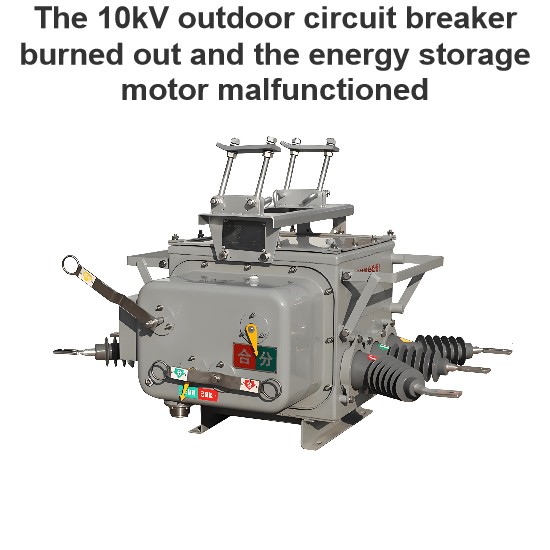
Additionally, in draw - out switch cabinets, the burning out of components such as energy - storage motors, Y3 relays, and rectifier bridges often occurs, which in turn leads to faults of the control circuit being open - circuited.
There are numerous issues in the control of the operating circuit. Loose terminal connections, poor contacts, and insulation problems of equipment can all cause defects, preventing the circuit breaker from operating properly for opening and closing. When an operating circuit fault occurs, the fault should first be located to identify its source, and then appropriate solutions should be implemented based on the specific situation.
Fault Phenomena and Treatment Methods of Mechanical Failures in Auxiliary and Actuating Mechanisms
When the circuit breaker cannot be opened or closed either electrically or manually, mechanically, the first step is to check whether the mechanism is properly energized. If the energy storage is normal, the problem may be caused by the loosening of the stop piece on the opening and closing half - shaft, insufficient stroke of the opening and closing push rod, or deformation of the opening and closing push rod, which results in jamming or sticking during the opening and closing process, preventing the circuit breaker from operating normally.
The fault can be addressed by readjusting the stroke of the push rod of the opening and closing coil, fixing the stop piece of the opening and closing half - shaft, and replacing or repairing the defective push rod (changing the copper opening and closing push rod to a steel one to avoid deformation). When the energy storage is abnormal or there are problems in the secondary circuit, the energy - storage motor, travel switch, and control circuit should be inspected for troubleshooting.
The actuating mechanism cannot be energized either electrically or manually. The main reasons are the damage of the one - way bearing in the energy - storage mechanism or the failure of the energy - storage latch to reset (the reset spring is not strong enough or foreign objects jam the reset spring), causing the energy - storage gear to idle. Such faults are prone to occur in CT19 - type mechanisms. The problem can be resolved by replacing the one - way bearing in the energy - storage mechanism or replacing (cleaning) the reset spring to restore normal energy storage.
If the opening and closing indication in the actuating mechanism does not match the actual opening and closing position of the circuit breaker body, it may be due to the disconnection of the connecting rod between the mechanism and the main transmission shaft of the circuit breaker. Manually adjust to align the position of the mechanism with that of the circuit breaker, and then reconnect and fix the transmission pull rod.

During the characteristic test, it is found that the low - voltage operation of the circuit breaker is unqualified. When the rated operating voltage is above 65%, the circuit breaker cannot perform reliable opening (it cannot open when the voltage is below 30%, and it may or may not open when the voltage is between 30% and 65%), and it should be able to close reliably at 85% - 110% of the rated voltage.
When this situation occurs, first check whether the resistance of the coil is within the qualified range. If it is qualified, clean the mechanism, add lubricant to the rotating parts, and then check the engaging depth of the opening and closing half - shaft. If it does not meet the requirements, adjust the adjusting screw for the engaging (inserting) depth of the opening and closing half - shaft (as shown in Figure 1) to meet the requirements (the engaging depth of the CT19 - type mechanism is generally 1 - 2mm).
In addition, an increase in the resistance of the closing coil leading to a decrease in the opening and closing coils, as well as deformation of the opening and closing push rods causing jamming or sticking during opening and closing, will all affect the opening and closing voltage. When dealing with problems, specific handling should be carried out according to the fault situation.
In the draw - out switch equipment, the draw - out switch cannot be moved from the test position to the operating position. The possible causes of such a fault include ground knife interlock failure, deformation of the ground knife interlock linkage plate, failure of the ground knife operation hole linkage plate to reset, and faults in the draw - out switch chassis. The draw - out switch can be moved to the maintenance position.
Check whether the tongue - shaped interlock plate of the ground knife is deformed or whether this tongue - shaped plate corresponds to the position of the ground knife; check whether the operation hole linkage plate is fully reset; remove the chassis of the draw - out switch and check whether all internal components are in good condition.
Routine Maintenance Measures for Circuit Breakers
When dealing with faults in the circuit breaker mechanism, first analyze the type of fault to determine whether it belongs to an electrical or secondary circuit problem or a mechanical fault, and then proceed with the next - step handling. The method for judging faults is relatively simple. First, make the mechanism fully energized.
If the circuit breaker can be reliably opened and closed manually, mechanical faults can be basically excluded. Then, perform electrical opening and closing. If the opening and closing electromagnets operate but the switch fails to open and close, and the secondary control voltage is normal, it indicates that there are no problems with the secondary circuit.
For more concealed faults such as reduced vacuum degree, out - of - synchronism in opening and closing, insufficient opening and closing speed, and large bounce, relevant scientific instruments must be used for testing and measurement during maintenance. Problems should be solved through the analysis and judgment of actual measurement data.
In addition to fault repair, certain maintenance work should also be carried out on vacuum circuit breakers in daily work. This includes cleaning the transmission mechanism and insulating support columns to avoid increasing rotational friction, and appropriately adding lubricant to ensure flexible operation. When the vacuum circuit breaker is under outage for maintenance, loop resistance and mechanical characteristic tests should be conducted, and damaged components caused by overheating, etc. of the circuit breaker should be dealt with in a timely manner.
The fault repair and maintenance work of 10kV circuit breakers has similarities with that of circuit breakers or transformers of other voltage levels in terms of mechanical and secondary circuit fault repair principles. By continuously accumulating experience, technical means can be continuously improved to achieve a better fault elimination rate and maintenance level.
Conclusion
With the rapid development of society, the demand for power supply in all walks of life is constantly increasing, and higher requirements are also put forward for the quality of power supply equipment and the operational stability of the power system. Technical levels and the ability to handle defects need to be continuously improved to meet the needs of development, satisfy the requirements of the majority of users, shorten the time for equipment defect handling and maintenance, and ensure the safe operation of the power grid.
Therefore, during the process of equipment maintenance and renovation, we should strengthen the study of the characteristics of system equipment itself, comprehensively understand the operational characteristics of equipment and the existing problems and potential hazards, strengthen learning and communication, take preventive measures in a timely manner, continuously improve equipment, eliminate safety hazards, prevent accidents, and ensure the safe operation of equipment and the reliability of power supply.
Hey there! I'm an electrical engineer specializing in Failure and Maintenance. I've dedicated my career to ensuring the seamless operation of electrical systems. I excel at diagnosing complex electrical failures, from malfunctioning industrial motors to glitchy power distribution networks. Using state - of - the - art diagnostic tools and my in - depth knowledge, I pinpoint issues quickly. On this platform, I'm eager to share my insights, exchange ideas, and collaborate with fellow experts. Let's work together to enhance the reliability of electrical setups.


