How to install the transition joint for the speed measurement rotating sensor of the 10 kV indoor vacuum circuit breaker?

James
06/09/2025

1 Innovation Background
Regular mechanical characteristic tests (covering closing/opening time, speed, opening distance, over - travel, three - phase asynchrony, bouncing time, etc.) are crucial for 10 kV indoor vacuum circuit breakers, ensuring reliable power supply and grid stability. Manufacturers typically use the moving - contact linear sensor method for testing, as it accurately reflects performance via consistent motion curves between the linear transmission rod and moving contacts.
To ease testing, manufacturers add sensor - connection screw holes and test racks. However, switchgear - installed propulsion chassis blocks the rod bottom, requiring rack - based sensor installation—often unavailable or impractical on - site without special equipment, making linear sensor handling laborious.While rotation sensors (needing travel parameter input) serve as workarounds, many breakers lack proper spindle - end holes for coupling. Thus, a new transition joint enables reliable rotation - sensor connection to the spindle, streamlining installation.
2 Innovative Technology of Transition Joint
2.1 Technical Requirements
To ensure the reliable connection between the rotation sensor and the end of the main shaft, the following three main problems must be solved:
  • After the transition joint is installed, it must ensure that the center line of the circuit breaker's crank arm main shaft is consistent with the axial center line of the sensor coupling, that is, to maintain coaxial center.
  • After the transition joint is fixed, the rotation angle must be consistent with that of the circuit breaker's crank arm main shaft during movement, and there should be no additional rotation other than the rotation of the main shaft, that is, to overcome the external rotation of the main shaft.
  • After the transition joint is fixed, there should be no axial movement. This is also the difficulty in solving the connection problem, that is, to suppress axial movement.
2.2 Solutions
(1) The machining accuracy tolerance of the outer circle of the circuit breaker's crank arm main shaft is controlled within 0.01 mm. Therefore, the outer circle of the main shaft can be fully used to position the center line of the transition joint, effectively maintaining coaxial center.
(2) Due to the need for assembling the crank arm, the circuit breaker's crank arm main shaft is processed with keyways with a width of 8 mm or 10 mm (with some variations), and the error is controlled within 0.01 mm, which can exactly match the outer diameter of 8.8 - grade M8 and M10 high - strength bolts, effectively overcoming the external rotation of the main shaft.
(3) After the transition joint is fixed, there are no components with large - scale axial movement or significant axial force. Fixing the transition joint onto the circuit breaker's crankshaft spindle with a circular thin - sheet strong magnet can counteract the axial displacement of the sensor caused by the circuit breaker's operational vibrations during measurement, effectively suppressing axial movement.
By making full use of the structural characteristics of the circuit breaker, we have successfully developed an axial magnetic - attraction fixed - type transition joint for the speed - measuring rotation sensor of the vacuum circuit breaker, which uses the outer circle of the crank arm main shaft to position the axis line.
As per the design scheme, a Q235A iron rod with a length of 60 mm and diameter of 40 mm is selected as the blank, which is machined into a circular full - enclosed structure on a lathe. The inner diameter of the front end is processed to 32 mm with a dimensional error controlled within 0.01 mm to ensure precise fitting with the spindle end; the tail is machined into a circular rod with a diameter of 12 mm for sensor connection. Two circular holes with an inner diameter of 8 mm are drilled on opposite sides of the body and tapped to fit the installation of M8 and M10 high - strength bolts.
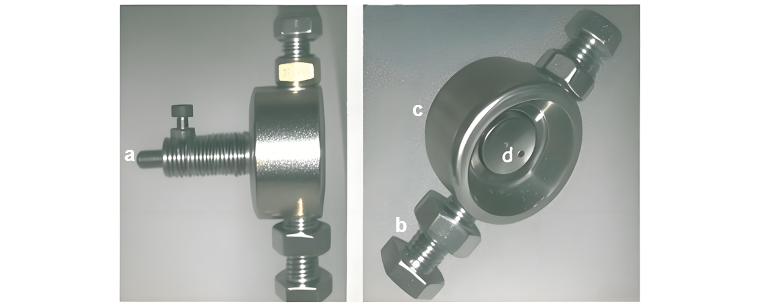
A strong magnetic sheet with a diameter of 16 mm and thickness of 2 mm is purchased. A hole is drilled on the tail circular rod of the body to machine a transition connecting rod for coupling with the shaft coupling. The finished structure is shown in Figure 1:
  • Component a: Connects with the shaft coupling to realize reliable fixation of the rotation sensor;
  • Component b: The outer diameter of M8/M10 high - strength bolts matches the keyway of the spindle end to eliminate extra rotation of the transition joint;
  • Component c: The outer circle of the transition joint matches the spindle outer circle to ensure coaxial alignment between the transition joint and the spindle;
  • Component d: The circular thin strong magnet fixes the transition joint to the circuit breaker crank arm spindle via magnetic attraction, overcoming the axial displacement of the sensor caused by vibrations during measurement and effectively suppressing axial movement.

3 Application Effect

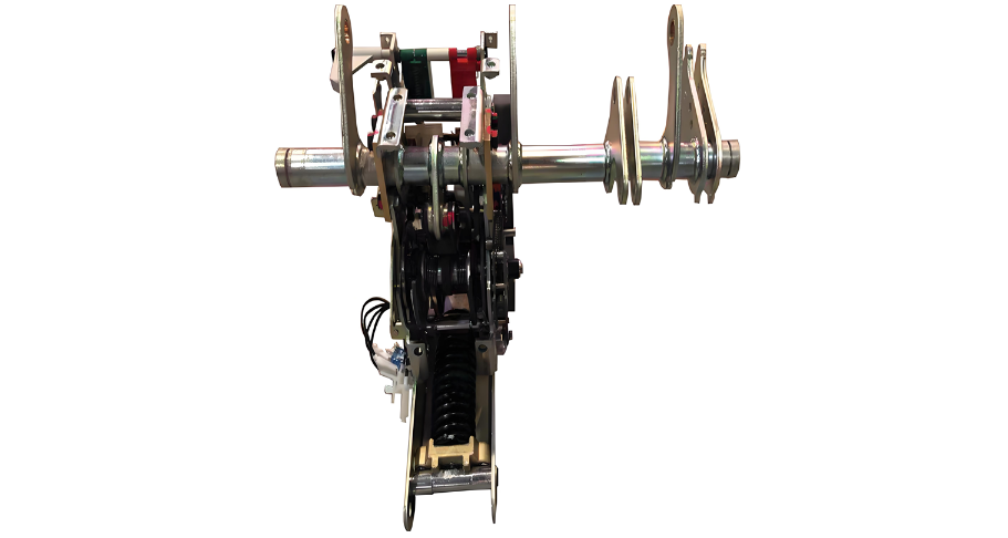
The overall assembly of the rotation sensor was completed using the transition joint, and the field test effect is shown in Figure 3. After the design and manufacture of the rotation sensor transition joint were completed, a VS1 - 12 indoor vacuum circuit breaker with a threaded hole for the rotation sensor transition joint at the shaft end was selected. Using the same circuit breaker mechanical characteristics tester, test comparisons were carried out respectively with the original transition joint and the transition joint for the installation of the rotation sensor with a lead screw.

When compared with the original transition joint, the difference in the three sets of self - inspection measurement data was within 2 decimal places (the actual measurement results retain 1 decimal place), indicating that the stability of this transition joint is good; when compared with the transition joint for lead screw installation, the difference in the three sets of measurement data was also within 2 decimal places (the actual measurement retains 1 decimal place), indicating that the measurement accuracy of its design meets the requirements.

In actual use, the wear of the ends of the M8 or M10 high-strength bolts that fit with the keyway is relatively prominent. Therefore, generally, 2 - 3 spare bolts are provided for each. If there is even a slight rotational clearance, they are replaced immediately. Usually, new bolts need to be replaced after testing about 30 units.

James

Professionalism builds strength. As an expert in the installation and operation of electrical equipment, I am proficient in the installation process and strictly adhere to standards. I skillfully master the operation essentials and can swiftly eliminate faults. With a heart that constantly explores new knowledge, I illuminate the path to the efficient operation of electrical equipment.

Inquiry
Download
Experts Electrical is dedicated to serving the personnel in the global power industry.
Join Experts Electrical, not only can you discover power equipment and power knowledge, but also canhnd like - minded friends!