Background of Transformer EMF Equation Derivation
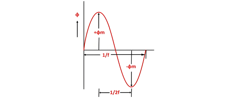
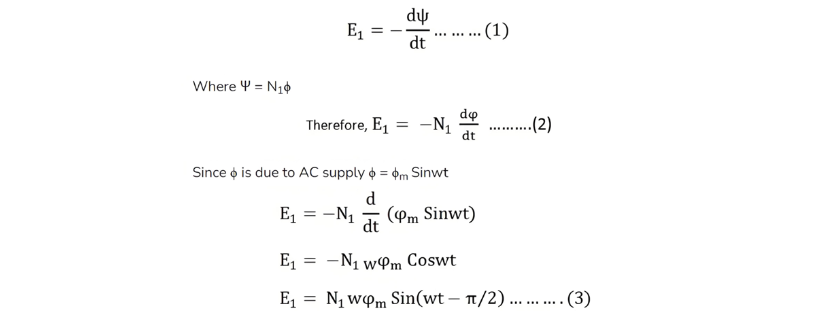
When a sinusoidal voltage is applied to the transformer's primary winding, an alternating flux ϕm is induced in the iron core. This sinusoidal flux links both primary and secondary windings, with its functional form described by a sine function.
Mathematical Derivation of Flux Rate of Change
The following outlines the derivation of the transformer's EMF equation, with defined parameters:
- ϕm: Maximum flux (Weber)
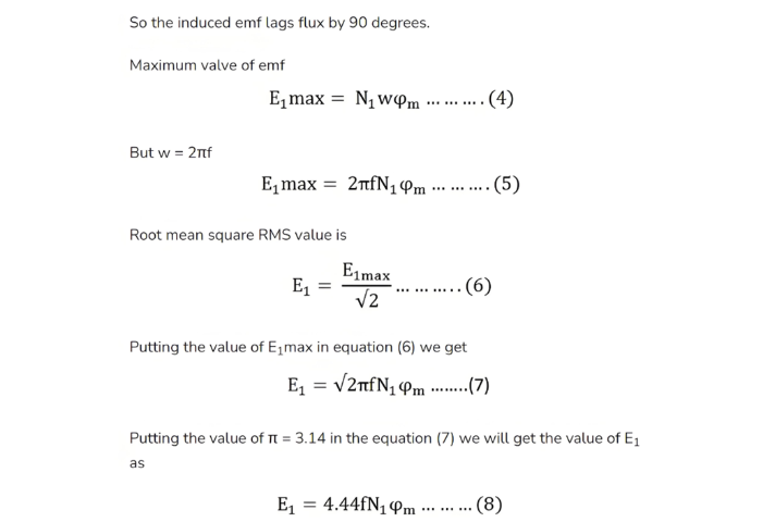
- f: Supply frequency (Hz)
- N1: Number of primary turns
- N2: Number of secondary turns
- Φ: Flux per turn (Weber)
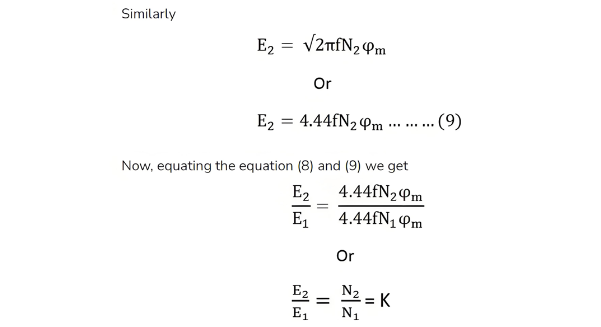
Turn Ratio and Flux Density Relation
The above equation is referred to as the turn ratio, where K denotes the transformation ratio.
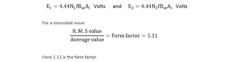
Using the relation ϕm=Bm×Ai (where Ai is the iron core cross-sectional area and Bm is the maximum flux density), Equations (8) and (9) can also be expressed as: