Transformer Resistance and Reactance Representation
Resistance Definition
The resistance of a transformer refers to the internal resistance of its primary and secondary windings, denoted as R1 and R2. Corresponding reactances are X1 and X2, with K representing the transformation ratio. To simplify calculations, impedances can be referred to either winding—either primary terms referred to the secondary side or vice versa.
Voltage Drops in Windings
Resistive and reactive voltage drops in primary and secondary windings are:
- Secondary resistive drop: I2R2
- Secondary reactive drop: I2X2
- Primary resistive drop: I1R1
- Primary reactive drop: I1X1
Primary-to-Secondary Referencing
When referring primary drops to the secondary side using transformation ratio K:
- Primary resistive/reactive drops become K⋅I1R1 and K⋅I1X.
- Substituting I1 = KI2, the referenced drops become:
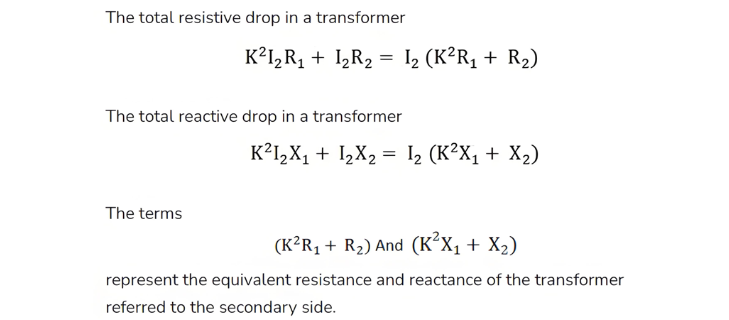
- Resistive: K2I2R1
- Reactive: K2I2X1
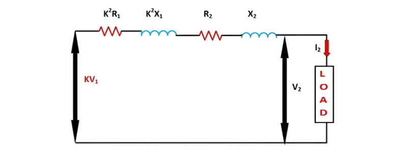
Therefore this will be the load voltage.