Calibration of Voltmeter, Ammeter & Wattmeter using Potentiometer

Edwiin
04/29/2025

Calibration is the process of verifying the accuracy of a result by comparing it with a standard value. In essence, it assesses the correctness of an instrument by contrasting it against a reference standard. This process enables us to identify errors in readings and make adjustments to voltages to achieve an ideal reading.

Calibration of Voltmeter
The circuit for the calibration of the voltmeter is shown in the figure below.

The circuit necessitates two rheostats: one serves to control the voltage, while the other is for fine - tuning. A voltage ratio box is employed to step - down the voltage to an appropriate level. The accurate value of the voltmeter is ascertained by measuring the voltage within the potentiometer's maximum possible range.
The potentiometer is capable of measuring the maximum achievable voltage values. If the readings of the potentiometer and the voltmeter do not match, negative or positive errors will manifest in the voltmeter's readings.
 
Calibration of Ammeter
The circuit for calibrating the ammeter is illustrated in the figure below.

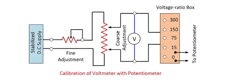
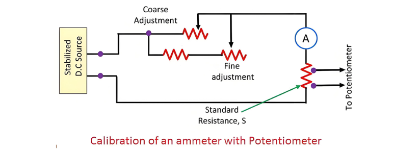
A standard resistance is connected in series with the ammeter that is to be calibrated. A potentiometer is utilized to measure the voltage across the standard resistor. The current flowing through the standard resistance is determined by the formula described below.

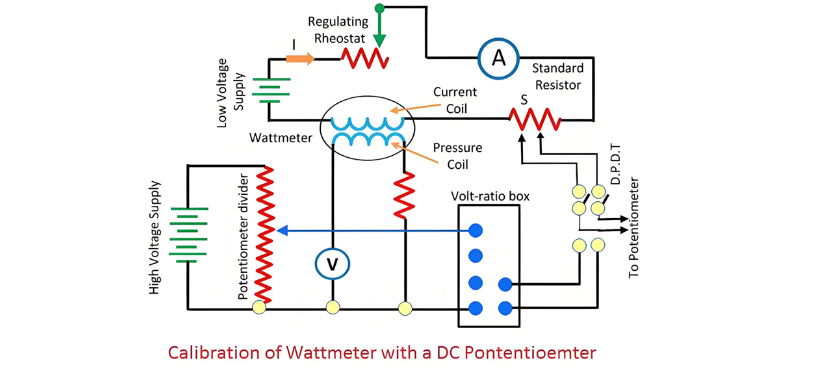
where:Vs is the voltage across the standard resistor, as measured by the potentiometer.S is the resistance value of the standard resistor.This approach to ammeter calibration is highly accurate. The reason lies in the fact that both the value of the standard resistance and the voltage measured by the potentiometer can be precisely determined by the measuring instruments.Calibration of WattmeterThe circuit employed for calibrating the wattmeter is depicted in the figure below.

A standard resistance is connected in series with the wattmeter that requires calibration. A low - voltage power source supplies current to the current coil of the wattmeter. A rheostat is connected in series with the coil to regulate the current value.
The potential circuit is powered by the electrical supply. A volt - ratio box is utilized to reduce the voltage to a level that can be conveniently measured by the potentiometer. The actual values of voltage and current are measured using a double - pole double - throw switch. Subsequently, the accurate product of voltage and current (VI) is compared with the reading of the wattmeter.
Edwiin

Load Frequency Control (LFC) & Turbine Governor Control (TGC) in Power System
Brief Introduction to Thermal Generating UnitsElectricity generation relies on both renewable and non - renewable energy resources. Thermal generating units represent a conventional approach to power production. In these units, fuels such as coal, nuclear energy, natural gas, biofuel, and biogas are combusted within a boiler.The boiler of a generating unit is an extremely complex system. In its simplest conception, it can be visualized as a chamber whose walls are lined with pipes, through which
Edwiin
06/06/2025
Why 3-Phase Power? Why Not 6, 12 or More for Power Transmission?
It is well-known that single-phase and three-phase systems are the most prevalent configurations for power transmission, distribution, and end-use applications. While both serve as fundamental power supply frameworks, three-phase systems offer distinct advantages over their single-phase counterparts.Notably, multi-phase systems (such as 6-phase, 12-phase, etc.) find specific applications in power electronics—particularly in rectifier circuits and variable frequency drives (VFDs)—wher
Edwiin
06/05/2025
How Many Poles and Towers are Situated Within a 1-km Span?
The number of distribution poles and transmission towers within a 1-kilometer stretch of overhead lines varies significantly based on multiple factors, including voltage level, power line type, supporting structure, geographical location, local regulations, and specific grid requirements.In urban areas, distribution utility poles are typically positioned at closer intervals, while in rural regions, they are spaced farther apart. Additionally, the use of taller structures for higher-voltage trans
Edwiin
06/05/2025
Synchronizing Power and Torque Coefficient
Definition of Synchronizing PowerSynchronizing power, denoted as Psyn, is defined as the variation in synchronous powerP with respect to changes in the load angle δ. Also referred to as thestiffness of coupling,stability factor, orrigidity factor, it quantifies a synchronous machine’s (generator or motor) inherent tendency to maintain synchronism when connected to infinite busbars.Principle of Synchronism MaintenanceConsider a synchronous generator transmitting a steady power Pa at a
Edwiin
06/04/2025
Inquiry
Download
Experts Electrical is dedicated to serving the personnel in the global power industry.
Join Experts Electrical, not only can you discover power equipment and power knowledge, but also canhnd like - minded friends!