What is Electrical Drive Systems?
Definition
An electrical drive system is defined as a mechanism designed to regulate the speed, torque, and direction of an electric motor. While each electrical drive system may possess unique characteristics, they also share several common features.
Electrical Drive Systems
The figure below illustrates the typical configuration of a plant - level power distribution network. In this setup, the electrical drive system draws its incoming alternating - current (AC) supply from a Motor Control Center (MCC). The MCC serves as a central hub, overseeing the power distribution to multiple drives situated within a specific area.
In large - scale manufacturing plants, numerous MCCs are often in operation. These MCCs, in turn, receive power from the main distribution center known as the Power Control Centre (PCC). Both the MCC and PCC commonly employ air circuit breakers as the primary power - switching elements. These switching components are engineered to handle electrical loads with ratings of up to 800 volts and 6400 amperes, ensuring reliable and efficient power management within the electrical drive system and the overall plant infrastructure.
The GTO inverter controlled induction motor drive is shown in the figure below:

Main Parts of Electrical Drive Systems
The following are the key components of these drive systems:
Incoming AC switch
Power converter and inverter assembly
Outgoing DC and AC switchgear
Control logic
Motor and the associated load
The main parts of the electrical power system are detailed below.
Incoming AC Switchgear
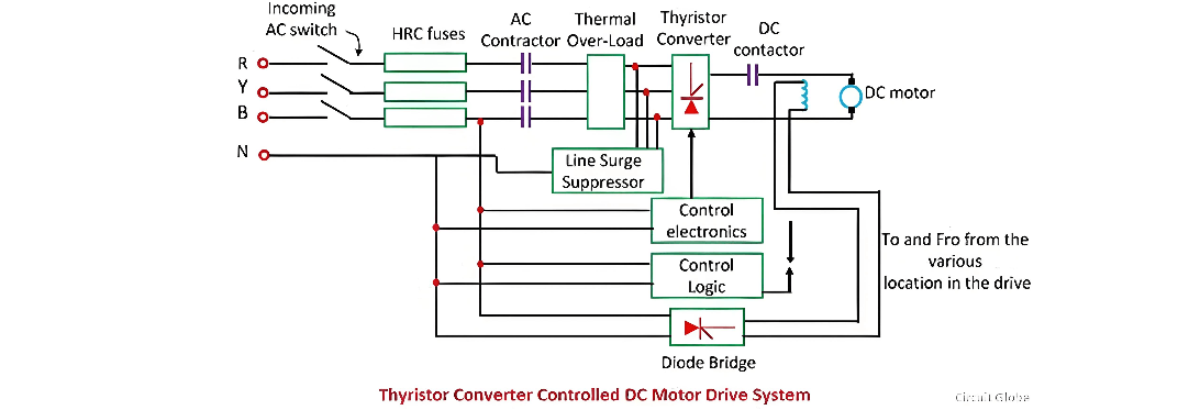
The incoming AC switchgear comprises a switch - fuse unit and an AC power contactor. These components typically have voltage and current ratings of up to 660V and 800A. Instead of a normal contactor, a bar - mounted contactor is often used, and an air circuit breaker serves as the incoming switch. The use of a bar - mounted contactor extends the rating capabilities up to 1000V and 1200A.
This switchgear is equipped with a High Rupturing Capacity (HRC) fuse rated for up to 660V and 800A. Additionally, it includes a thermal overload protection mechanism to safeguard the system from overloading. In some cases, the contactor of the switchgear can be replaced with a moulded case circuit breaker for enhanced performance and protection.
Power Converter/Inverter Assembly
This assembly is divided into two major sub - blocks: power electronics and control electronics. The power electronics block consists of semiconductor devices, heat sinks, semiconductor fuses, surge suppressors, and cooling fans. These components work together to handle the high - power conversion tasks.
The control electronics block includes a triggering circuit, its own regulated power supply, and a driving and isolation circuit. The driving and isolation circuit is responsible for controlling and regulating the power flow to the motor.
When the drive operates in a closed - loop configuration, it includes a controller along with current and speed feedback loops. The control system features three - port isolation, ensuring that the power supply, inputs, and outputs are isolated with appropriate insulation levels to enhance safety and reliability.
Line Surge Suppressors
Line surge suppressors play a crucial role in protecting the semiconductor converter from voltage spikes. These spikes can occur in the power line due to the switching on and off of loads connected to the same line. The line surge suppressor, in combination with inductance, effectively suppresses these voltage spikes.
When the incoming circuit breaker operates and interrupts the current supply, the line surge suppressor absorbs a certain amount of trapped energy. However, if the power modulator is not a semiconductor device, a line surge suppressor may not be necessary.
Control Logic
Control logic is used for interlocking and sequencing the various operations of the drive system under normal, fault, and emergency conditions. Interlocking is designed to prevent abnormal and unsafe operations, ensuring the system's integrity. Sequencing, on the other hand, ensures that drive operations such as starting, braking, reversing, and jogging are carried out in a pre - determined sequence. For complex interlocking and sequencing tasks, a programmable logic controller (PLC) is often employed to provide flexible and reliable control.
The Electricity Encyclopedia is dedicated to accelerating the dissemination and application of electricity knowledge and adding impetus to the development and innovation of the electricity industry.

